chipKIT® Development Platform
Inspired by Arduino™
- Get Started
- Learning
- Products
- Blog
- Beginner
For first time users of chipKIT modules. - Intermediate
For users who have a moderate exposure with chipKIT modules. - Advanced
For users who are experts with chipKIT modules. - Developers
- About Us
- Support
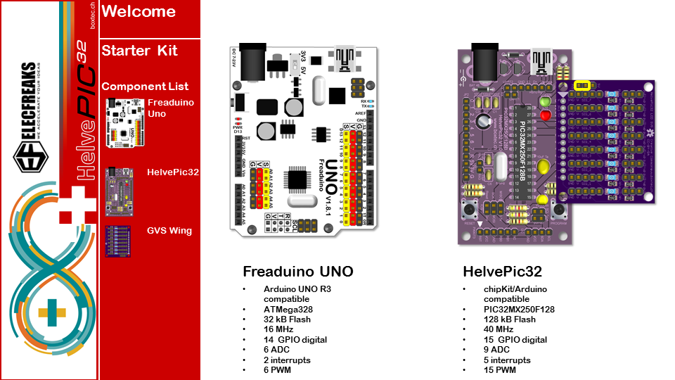
Starter Kit
An Arduino StarterKit?
The chipKit is code compatible to the Arduino. This means that you can use Arduino Code and run it on the chipKit board using the hardware you may already have with the Arduino.
There is no discussion of you should use the chipKit OR the Arduino - it is chipKit AND Arduino!
To emphasize the similarities I took the inexpensive starter kit from Elecfreaks and described the usage on either the Arduino (Freaduino) or the HelvePic32. It also illustrates how small the changes are that need to be applied to the code.
The HelvePic32 is a chipKit board that you can solder yourself from scratch without SMD parts or difficult elements. It is intended for beginners and kids to learn to build and control electronics from the bottom up.
The pinmap definitions are included in the HelvePic32 library.
All code examples are available as download.
The kit can be ordered at www.boxtec.ch or Robotshop and of course at Elecfreaks directly. Other distributors may be available in Europe as well.
All examples can be done using the HelvePic32 alone but we created a small GVS-led-Wing that adds Ground, Vcc and Signal Pins to each pin of a side plus a LED and pull-up/down resistors selectable via jumpers.
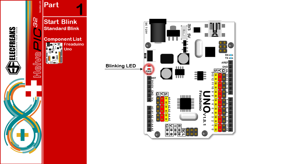
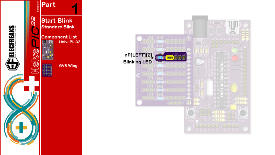
Let's start with the standard blink example.
Standard Blink Example
/* part1 ARDUINO START Turns on an LED on for one second, then off for one second, repeatedly.
This example code is in the public domain. */
// Pin 13 has an LED connected on most Arduino boards. // give it a name: #if defined(AVR) int led = 13; #elif defined(PIC32MX) #include <HelvePic32.h> int led = nP[LEFT][2]; #endif
// the setup routine runs once when you press reset: void setup() { // initialize the digital pin as an output. pinMode(led, OUTPUT); }
// the loop routine runs over and over again forever: void loop() { digitalWrite(led, HIGH); // turn the LED on (HIGH is the voltage level) delay(1000); // wait for a second digitalWrite(led, LOW); // turn the LED off by making the voltage LOW delay(1000); // wait for a second }
Button Controlled LED
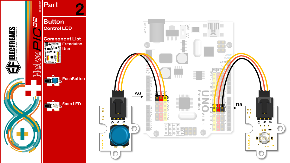
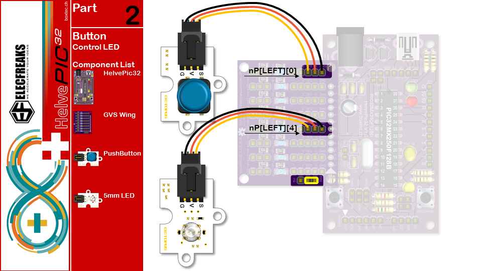
/part2 USE BUTTON CONTROL LED Press the button, led lights, then press the button led is off/ #if defined(AVR) int led = 5;// The 5 pin,driving LED int button = A0;// The A0 pin,read the button #elif defined(PIC32MX) #include int led = nP[LEFT][4]; int button = nP[LEFT][0]; #endif
void setup() {
pinMode(led, OUTPUT);// initialize the LED pin as an output.
pinMode(button, INPUT_PULLUP);// initialize the BUTTON pin as an input.
}
void loop() {
if(digitalRead(button)==LOW){
delay(200);// wait for 200 microsecond,Avoid pressing the button and read many times in this very short time
digitalWrite(led, HIGH); // turn the LED on (HIGH is the voltage level)
while(1){
if(digitalRead(button)==LOW){
delay(200);
digitalWrite(led, LOW); // turn the LED off (LOW is the voltage level)
break; //End of the while loop,Back to the main loop
}
}
}
}
Vibration Controlled Buzzer
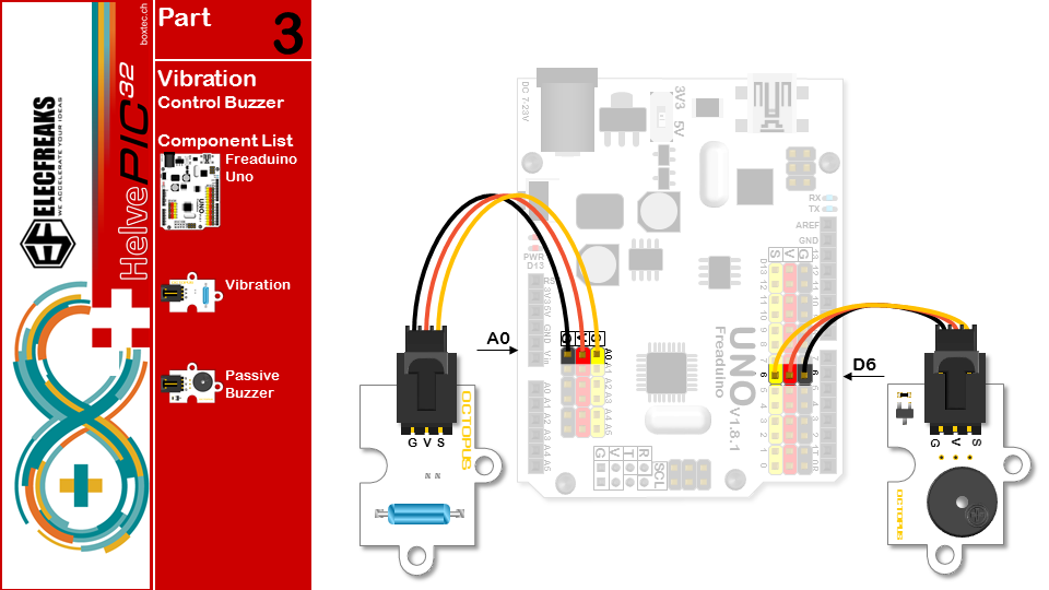
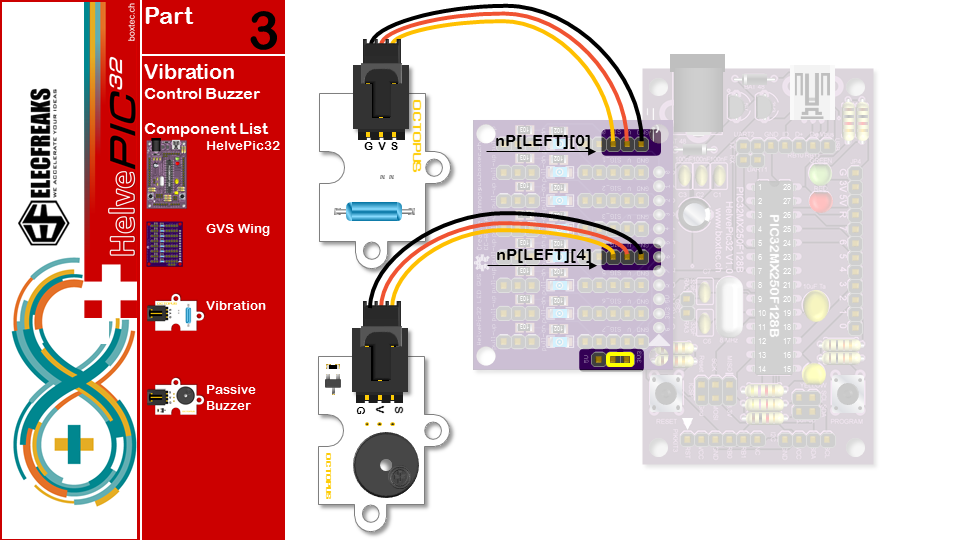
/*part3 USE Vibration sensors CONTROL Passive buzzer Knock on the table, the buzzer will ring */ #if defined(AVR) int vibration = A0;// The A0 pin,read Vibration sensors int buzzer = 6;// The 6 pin,driving the Passive buzzer,the pin must PWM out(3 5 6 9 10 11) #elif defined(PIC32MX) #include int vibration = nP[LEFT][0]; int buzzer = nP[LEFT][4]; #endif void setup() { pinMode(vibration,INPUT_PULLUP);// initialize the vibration pin as an input. pinMode(buzzer,OUTPUT);// initialize the buzzer pin as an output. } void loop() { if(digitalRead(vibration)==HIGH) { tone(buzzer,600,1000); delay(1000); } }
Motion (PIR) Controlled Fan
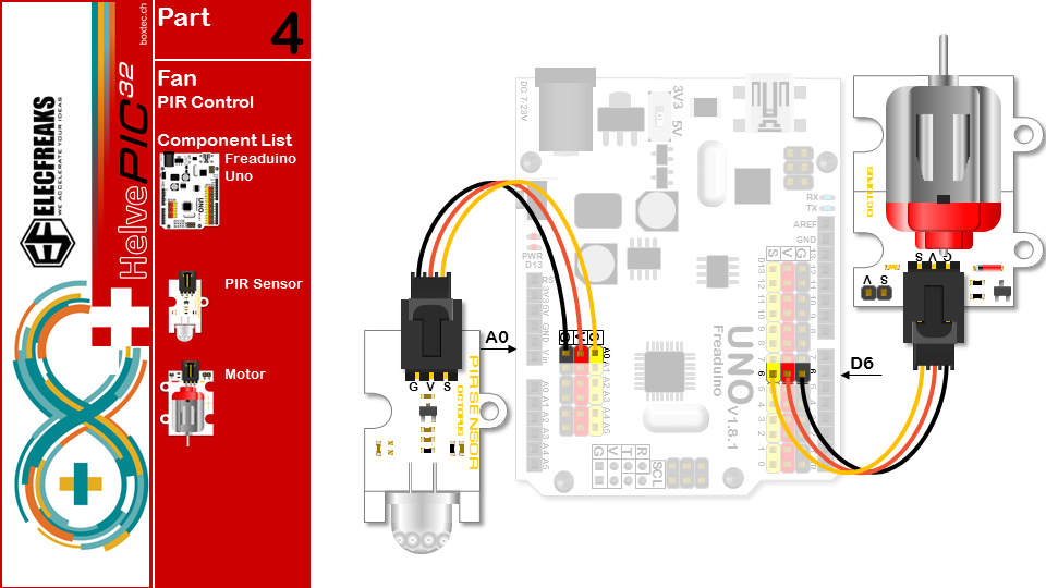
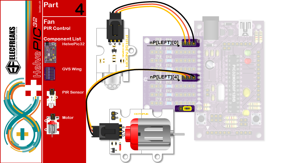
/*part4 USE PIR CONTROL Motor If someone passing from the front, the motor will turn */ #if defined(AVR) int pir = A0;// The A0 pin,,read PIR int motor = 6;// The 6 pin,driving the motor #elif defined(PIC32MX) #include int pir = nP[LEFT][0]; int motor = nP[LEFT][4]; #endif void setup() { pinMode(pir,INPUT_PULLUP);// initialize the vibration pin as an input. pinMode(motor,OUTPUT);// initialize the buzzer pin as an output. } void loop() { if(digitalRead(pir)==HIGH) { digitalWrite(motor,HIGH); delay(1000); digitalWrite(motor,LOW); } }
Light (LDR) Controlled Fan
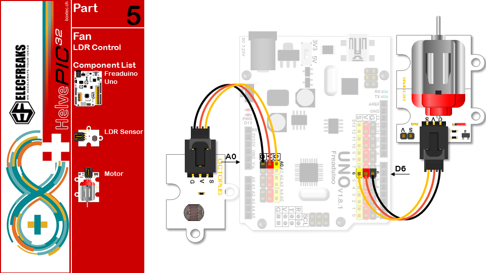
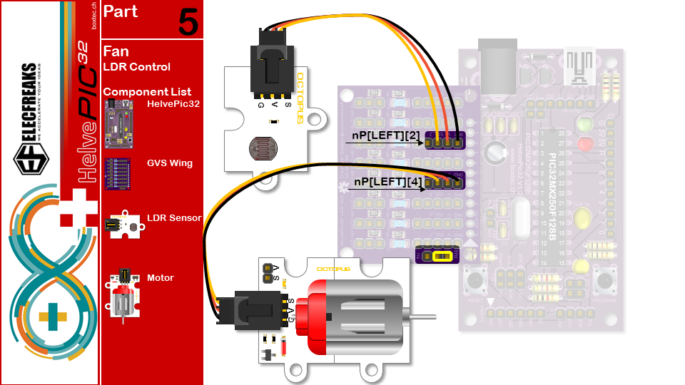
/*part5 USE Photodiode CONTROL Motor
According to the intensity of light motor speed control */
#if defined(AVR)
#define myWrite analogWrite
#define MAXLDR 512
#define MAXSPD 1024
int photodiode = A0;// The A0 pin,,read PIR
int motor = 6;// The 6 pin,driving the motor
#elif defined(PIC32MX)
#include
#include
#define myWrite SoftPWMServoPWMWrite
#define MAXLDR 1024
#define MAXSPD 255
int photodiode = nP[LEFT][2];
int motor = nP[LEFT][4];
#endif
void setup() {
pinMode(photodiode,INPUT);// initialize the photodiode pin as an input.
pinMode(motor,OUTPUT);// initialize the motor pin as an output.
}
void loop() {
int speed=map(analogRead(photodiode),0,MAXLDR,0,MAXSPD);//because the read max value is 512
myWrite(motor,speed);//According to the intensity of light motor speed control
}
Soil Moisture Controlled Relay
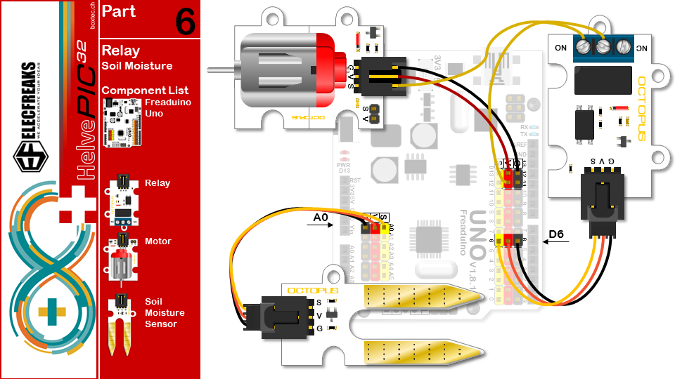
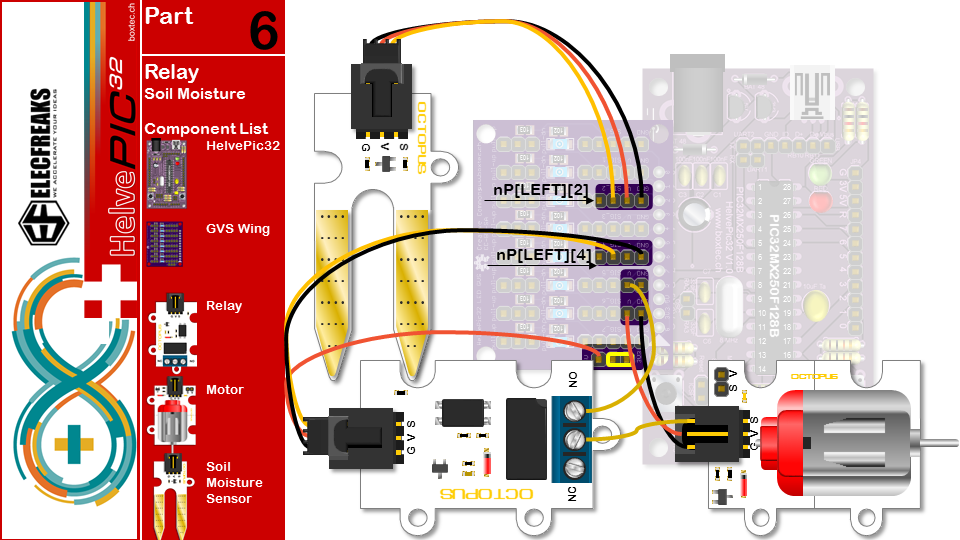
/*part6 USE Soil moisture CONTROL Relay According to the intensity of light motor speed control */ #if defined(AVR) int soil = A0;// The A0 pin,,read Soil moisture int relay = 6;// The 6 pin,driving the Relay #elif defined(PIC32MX) #include int soil = nP[LEFT][2]; int relay = nP[LEFT][4]; #endif
void setup() {
pinMode(soil,INPUT);// initialize the soil pin as an input.
pinMode(relay,OUTPUT);// initialize the relay pin as an output.
}
void loop() {
int value=analogRead(soil);
if(value>200){//set the default value ,you can set it then more or less to do something
digitalWrite(relay,HIGH);//turn on the relay
}
else digitalWrite(relay,LOW);//turn off the relay
}
Encoder Controlled servo
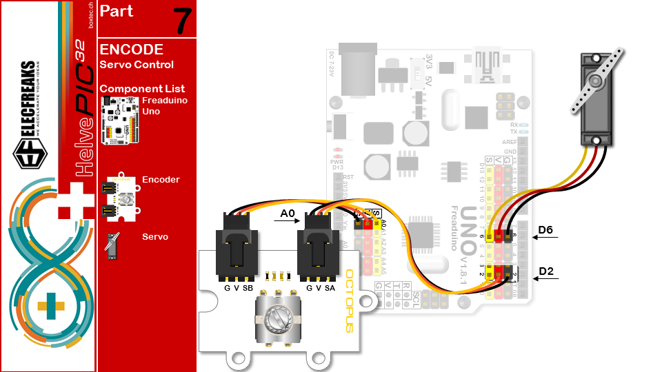
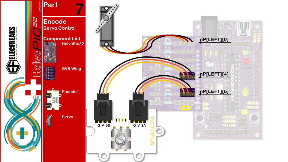
/*part7 USE encode CONTROL Servos Turn the rotary encoder control servos */ #if defined(AVR) #include //load servo library #define encodeB A0// The A0 pin,read encodeB int servos = 6;// The 6 pin,driving the servos Servo servo;//Get a servo controller #define INTNR 0 #elif defined(PIC32MX) #include #include int encodeB = nP[LEFT][4]; int servos = nP[LEFT][0]; #define INTNR 2 #endif
volatile int angle=90;//set the servo default angle
void setup() {
pinMode(encodeB,INPUT);// initialize the encodeB pin as an input.
#if defined(AVR)
servo.attach(servos);
servo.write(angle);
#elif defined(PIC32MX)
SoftPWMServoInit();
SoftPWMServoSetFrameTime(100000);
SoftPWMServoSetServoFrames(8);
SoftPWMServoServoWrite(servos, 10*angle+500);
#endif
attachInterrupt(INTNR,start,FALLING);//set encodeA interrupt,this board interrupt0 is pin 2
}
void loop() {
}
void start(){ if(digitalRead(encodeB)==HIGH) else angle+=3; if(angle>=180)angle=180; else if(angle<=0)angle=0; #if defined(AVR) servo.write(angle); #elif defined(PIC32MX) SoftPWMServoServoWrite(servos, 10*angle+500); #endif }
7-Segemnt Display and DHT11
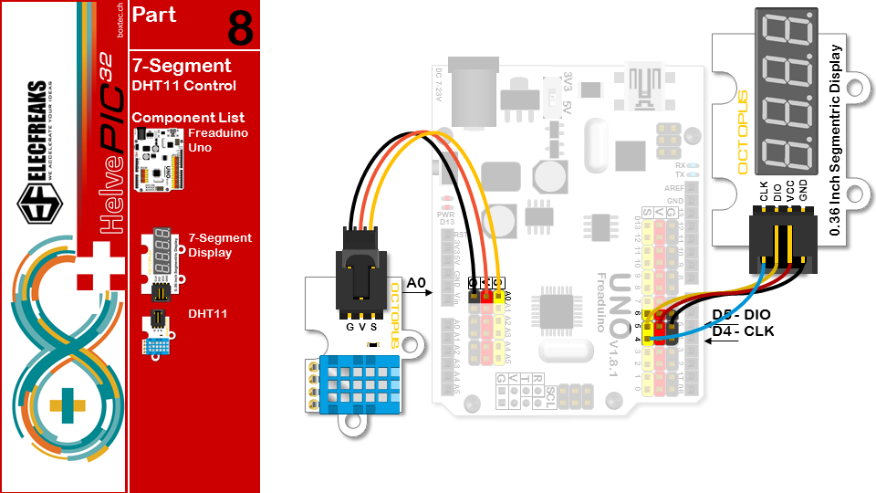
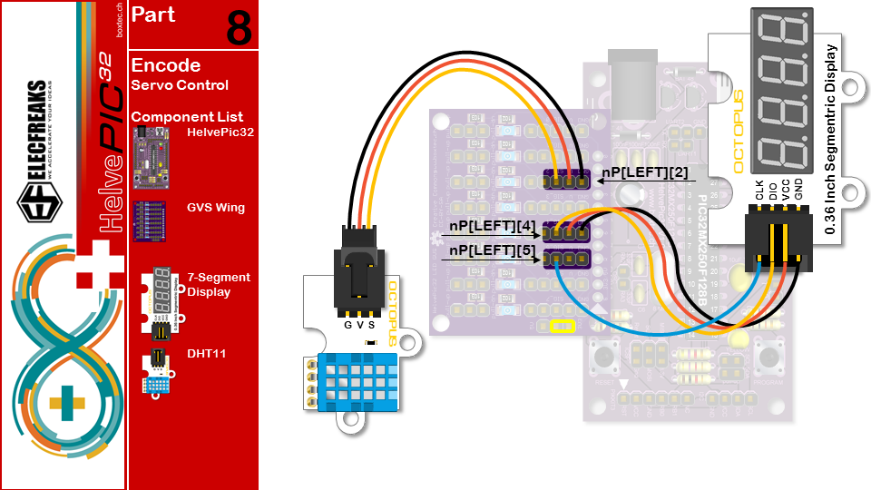
/* Part 8 USE DHT11 Temperature and humidity sensor and Segment
- display Temperature and humidity*/
#include "DHT11.h" //load Temperature and humidity sensor library
#include "TM1637.h"//load Segment display library
#if defined(AVR)
#define DHT A0
#define CLK 4//pins definitions clk for TM1637
#define DIO 5//pins definitions dio for TM1637
#elif defined(PIC32MX)
#include
#define DHT nP[LEFT][2]
#define CLK nP[LEFT][5]
#define DIO nP[LEFT][4]
#endif
TM1637 tm1637(CLK,DIO);//get Segment display controler
DHT11 dht11(DHT);//DHT11 A0
void setup(){
tm1637.init();
tm1637.set(BRIGHT_TYPICAL);
}
void loop(){
dht11.start();
tm1637.display(3,12);//Temperature Unit
tm1637.display(2,(dht11.DHT11data)[2]%10);
tm1637.display(1,(dht11.DHT11data)[2]%100/10);
delay(1000);
tm1637.clearDisplay();
tm1637.display(3,(dht11.DHT11data)[0]%10); // humidity
tm1637.display(2,(dht11.DHT11data)[0]%100/10); delay(1000); }
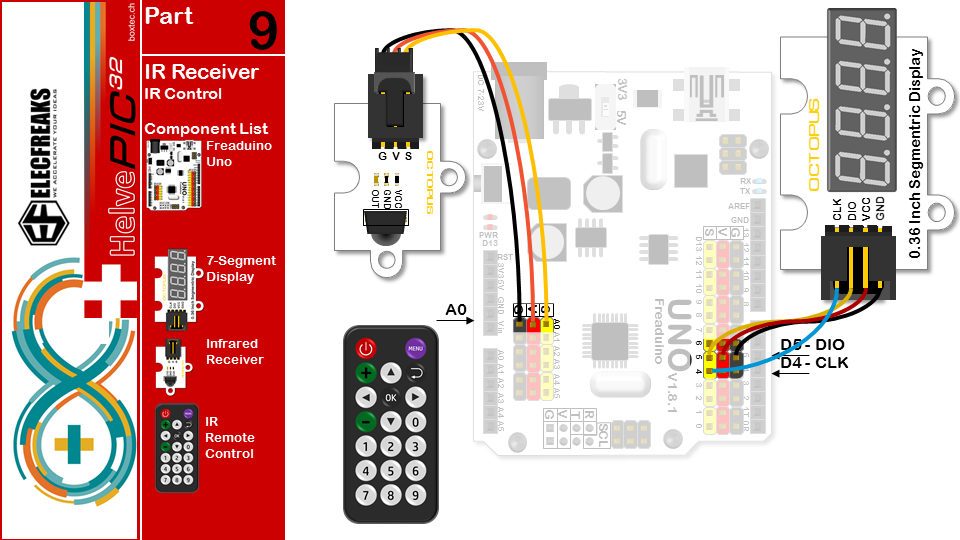
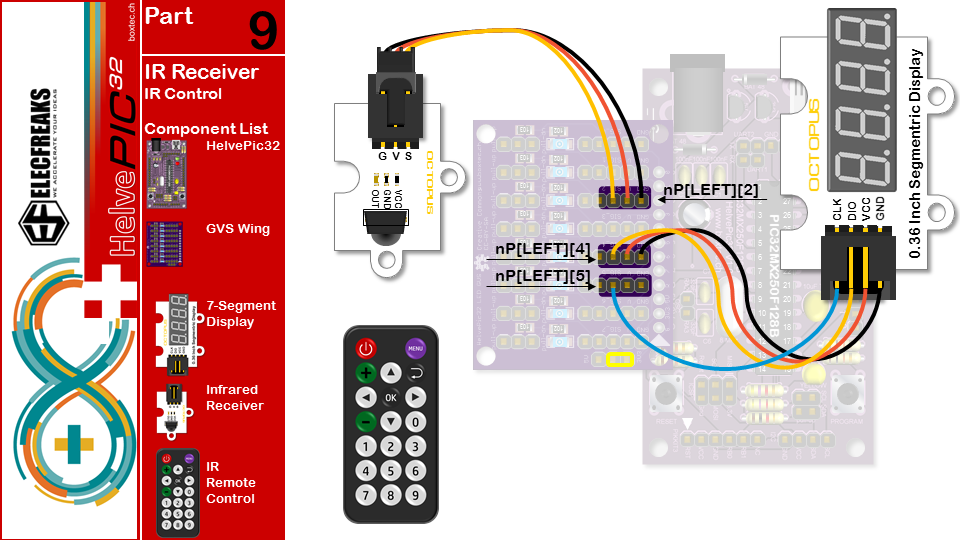
InfraRed Receiver
Unfortunately, the IRremote library has not (yet) been ported to the chipKit platform. This is due to the fact, that the library uses Arduino (AVR) specific machine code to optimize the signal reading.
On chipKit, this is significantly simpler I have split the code in two: the arduino code and the HelvePic32 code.
Arduino Code
/* Part9 USE IRreceive and IR remote Displayed on the segment code */ #include //load IRremote library #include "TM1637.h"//load Segment display library #define IRP A0 #define CLK 4//pins definitions clk for TM1637 #define DIO 5//pins definitions dio for TM1637
TM1637 tm1637(CLK,DIO);//get Segment display controler
IRrecv ir(IRP);//an instance of the IR receiver object, IRR is IRreceive pin;
decode_results result; // container for received IR codes
long codes[10]= // this array is used to store infrared codes
{
0xFD708F,0xFD08F7,0xFD8877,0xFD48B7,0xFD28D7,0xFDA857, //0 1 2 3 4 5
0xFD6897,0xFD18E7, 0xFD9867,0xFD58A7}; // 6 7 8 9
void setup(){
tm1637.init();
tm1637.set(BRIGHT_TYPICAL);
ir.enableIRIn();
}
void loop(){
if(ir.decode(&result)){
int i=-1;
while(!(i>9||result.value==codes[++i]));
ir.resume(); // resume receiver
if(i<10){
tm1637.clearDisplay();
tm1637.display(3,i);//IRremote value
}
}
}
HelvePic32 Code
/* Raw IR decoder sketch! */ #include #include "TM1637.h"//load Segment display library #define IRpin_PIN PORTA //PORTD #define IRpin 0 // 8 #define MAXPULSE 65000 #define RESOLUTION 20 #define MAXKEYS 20 #define CLK nP[LEFT][5] #define DIO nP[LEFT][4]
TM1637 tm1637(CLK,DIO);//get Segment display controler uint16_t pulses[100][2]; // pair is high and low pulse uint8_t currentpulse = 0; // index for pulses we're storing
void setup(void) { tm1637.init(); tm1637.set(BRIGHT_TYPICAL); Serial.begin(9600); Serial.println("Ready to decode IR!"); }
void loop(void) { uint16_t highpulse, lowpulse; // temporary storage timing highpulse = lowpulse = 0; // start out with no pulse length while (IRpin_PIN & (1 << IRpin)) { highpulse++; delayMicroseconds(RESOLUTION); if ((highpulse >= MAXPULSE) && (currentpulse != 0)) { printpulses(); currentpulse=0; return; } } pulses[currentpulse][0] = highpulse; while (! (IRpin_PIN & _BV(IRpin))) { lowpulse++; delayMicroseconds(RESOLUTION); if ((lowpulse >= MAXPULSE) && (currentpulse != 0)) { printpulses(); currentpulse=0; return; } } pulses[currentpulse][1] = lowpulse; currentpulse++; }
void printpulses(void) { int code = -1; const uint32_t CODES[] = { 0xE21D7E00, // 0 0xDE217E00, // 1 0xDC237E00, // 2 0xDA257E00, // 3 0xD6297E00, // 4 0xD42B7E00, // 5 0xD22D7E00, // 6 0xCE317E00, // 7 0xCC337E00, // 8 0xCA357E00, // 9 0xF6097E00, // + 0xE6197E00, // - 0xF40B7E00, // up 0xE41B7E00, // down 0xEE117E00, // left 0xEA157E00, // right 0xEC137E00, // ok 0xF20D7E00, // return 0xFA057E00, // menu 0xFE017E00 }; //power uint32_t IRid=0; uint8_t cnt=0; uint16_t p1, p2, d; for (uint8_t i = 1; i < currentpulse-1; i++) { if (i<32) else { // 0 IRid &= ~(1 << i); } } } Serial.print(IRid, HEX); Serial.print(" "); for (uint8_t i=0; i<MAXKEYS; i++) { if (IRid == CODES[i]) code = i; } Serial.println(code); tm1637.clearDisplay(); tm1637.display(3,code%10); tm1637.display(2,code%100/10); }