chipKIT® Development Platform
Inspired by Arduino™
- Get Started
- Learning
- Products
- Blog
- Beginner
For first time users of chipKIT modules. - Intermediate
For users who have a moderate exposure with chipKIT modules. - Advanced
For users who are experts with chipKIT modules. - Developers
- About Us
- Support
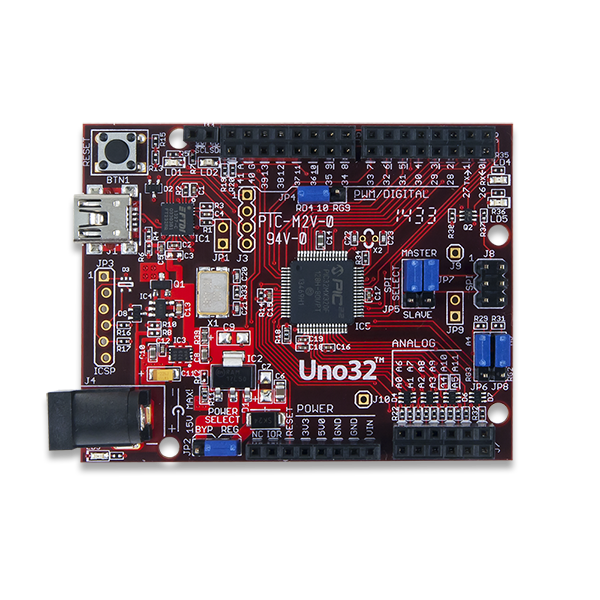
ChipKIT Uno32
| chipKIT Uno32 | |
|---|---|
 | |
| Specifications | |
| Controller | PIC32MX320F128H |
| Flash | 128kB |
| RAM | 16kB |
| Speed | 80MHz |
| Information | |
| Board Define | _BOARD_UNO_ |
| Links | |
| Designer | Digilent Inc. |
| Product Page | digilentinc.com |
| User Guide | chipkit_uno32_rm.pdf |
| Schematic | chipkit_uno32_sch.pdf |
| Tech Support | chipkit.net/forum |
| Board Files | Eagle (ZIP) |
| Bootloader HEX | Bootloader Image (ZIP) |
| Purchase From | Discontinued |
Note: Discontinued and replaced by chipKIT™ uC32 .
chipKIT™ Uno32 by Digilent is an easy-to-use platform for developing microcontroller-based applications. It uses chipKIT-core™ development environment and Arduino IDE for compatibility with existing code examples, tutorials and resources. Pin-compatible with many Arduino shields that can operate at 3.3V.
The Board Design
- PIC32MX320F128H processor with 128K Flash, 16K RAM
- Up to 80 MHz operating speed
- 42 available I/O lines
- USB or externally powered
- USB cable required for programming (not included)
Useful Board Pins
LEDs
| LED Name | Description |
|---|---|
| LD1 | USB TX Activity LED |
| LD2 | USB RX Activity LED |
| LD3 | 3.3V Power Indicator |
| LD4 | Digital pin 13 |
| LD5 | Digital pin 43 |
Analog Inputs
| Analog Input | Digital Pin |
|---|---|
| A0 | 14 |
| A1 | 15 |
| A2 | 16 |
| A3 | 17 |
| A4 | 18 |
| A5 | 19 |
| A6 | 20 |
| A7 | 21 |
| A8 | 22 |
| A9 | 23 |
| A10 | 24 |
| A11 | 25 |
Serial Objects
| Serial Object | UART | TX Pin | RX Pin |
|---|---|---|---|
| Serial | USB/UART1 | 1 | 0 |
| Serial1 | UART2 | 40 | 39 |
I2C
I2C SCK pin is Digial 46, and SDA is Digital 45.
The pins are shared with analong pins A4 and A5 and must be selected using jumpers JP6 and JP8. For JP6 and JP8: Short Pins 1&2 for Analog input mode and Pins 2&3 for I2C mode.
The default and an additional I2C port are available using the DTWI library. DTWI0 uses pins SCL (46) and SDA (45). DTWI1 uses pins SCL (40) and SDA (39).
SPI
SPI SS is Digital 10, MOSI is Digital 11, MISO is Digital 12, CLK is Digital 13.
Jumpers JP5 and JP7 are used to select whether the uC32 operates as a Master (transmit on MOSI, receive on MISO) or a Slave (transmit on MISO, receive on MOSI) device.
Jumper JP4 is used to select PWM output or the SPI SS function on pin 10. The shorting block on JP4 should be in the RD4 position to select PWM output.
Pinout Table
Quick reference: There are two user LEDs (Pin 11, Pin 43), and 12 analog inputs (Pin 14 - Pin 25, A0 - A11). All 47 are usable as GPIO, however some may be in use when used with the Arduino platform.
| chipKIT Pin # | Connector Pin # | PIC32 Pin # | PIC32 Signal | Notes |
|---|---|---|---|---|
| 0 | J6-01 | 34 | U1RX/SDI1/RF2 | |
| 1 | J6-03 | 33 | U1TX/SDO1/RF3 | |
| 2 | J6-05 | 42 | IC1/RTCC/INT1/RD8 | |
| 3 | J6-07 | 46 | OC1/RD0 | |
| 4 | J6-09 | 59 | RF1 | |
| 5 | J6-11 | 49 | OC2/RD1 | |
| 6 | J6-13 | 50 | OC3/RD2 | |
| 7 | J6-15 | 43 | IC2/U1CTS/INT2/RD9 | |
| 8 | J5-01 | 44 | IC3/PMCS2/PMA15/INT3/RD10 | |
| 9 | J5-03 | 51 | OC4/RD3 | |
| 10 | J5-05 | 52 | PMWR/OC5/IC5/CN13/RD4 | Selected by JP4, also on J8-6 |
| 11 | J5-07 | 6 | SDO2/PMA3/CN10/RG8 | Selected by JP5, also on J8-1 |
| 12 | J5-09 | 5 | SDI2/PMA5/CN8/RG7 | Selected by JP7, also on J8-4 |
| 13 | J5-11 | 4 | SCK2/PMA5/CN8/RG6 | Also on J8-3, User LED LD4 |
| 14/A0 | J7-01 | 14 | C2IN-/AN2/SS1/CN4/RB2 | |
| 15/A1 | J7-03 | 12 | C1IN-/AN4/CN6/RB4 | |
| 16/A2 | J7-05 | 21 | U2CTS/C1OUT/AN8/RB8 | |
| 17/A3 | J7-07 | 23 | TMS/CVREFOUT/PMA13/AN10/RB10 | |
| 18/A4 | J7-09 | 27 | TCK/PMA11/AN12/RB12 | Selected by JP6 |
| 19/A5 | J7-11 | 29 | PMALH/PMA1/U2RTS/AN14/RB14 | Selected by JP8 |
| 20/A6 | J7-02 | 13 | C2IN+/AN3/CN5/RB3 | |
| 21/A7 | J7-03 | 11 | C1IN+/AN5/CN7/RB5 | |
| 22/A8 | J7-06 | 22 | PMA7/C2OUT/AN9/RB9 | |
| 23/A9 | J7-08 | 24 | TDO/PMA12/AN11/RB11 | |
| 24/A10 | J7-10 | 28 | TDI/PMA10/AN13/RB13 | |
| 25/A11 | J7-12 | 30 | PMALL/PMA0/AN15/OCFB/CN12/RB15 | |
| 26 | J6-02 | 60 | PMD0/RE0 | |
| 27 | J6-04 | 61 | PMD1/RE1 | |
| 28 | J6-06 | 62 | PMD2/RE2 | |
| 29 | J6-08 | 63 | PMD3/RE3 | |
| 30 | J6-10 | 64 | PMD4/RE4 | |
| 31 | J6-12 | 1 | PMD5/RE5 | |
| 32 | J6-14 | 2 | PMD6/RE6 | |
| 33 | J6-16 | 3 | PMD7/RE7 | |
| 34 | J5-02 | 53 | PMRD/CN14/RD5 | |
| 35 | J5-04 | 45 | IC4/PMCS1/PMA14/INT4/RD11 | |
| 36 | J5-06 | 54 | CN15/RD6 | |
| 37 | J5-08 | 55 | CN16/RD7 | |
| 38 | J5-10 | 35 | U1RTS/BCLK1/SCK1/INT0/RF6 | |
| 39 | J5-12 | 31 | PMA9/U2RX/SDA2/CN17/RF4 | |
| 40 | J5-14 | 32 | PMA8/U2TX/SCL2/CN18/RF5 | |
| 41 | J5-16 | 15 | PGC1/AN1/VREF-/CVREF-/CN3/RB1 | |
| 42 | J5-15 | 16 | PGED1/PMA6/AN0/VREF+/CVREF+/CN2/RB0 | |
| 43 | N/A | 58 | RF0 | User LED LD5 |
| 44 | J5-05 | 8 | PMA2/SS2/CN11/RG9 | Selected by JP4, also on J8-6 |
| 45 | J11-1, J7-09 | 36 | SDA1/RG3 | Selected by JP6 |
| 46 | J11-2, J7-11 | 37 | SCL1/RG2 | Selected by JP8 |