chipKIT® Development Platform
Inspired by Arduino™
- Get Started
- Learning
- Products
- Blog
- Beginner
For first time users of chipKIT modules. - Intermediate
For users who have a moderate exposure with chipKIT modules. - Advanced
For users who are experts with chipKIT modules. - Developers
- About Us
- Support
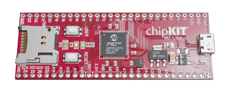
ChipKIT MZ Lite
| chipKIT MZ Lite | |
|---|---|
 | |
| Specifications | |
| Controller | PIC32MZ0512EFE064 |
| Flash | 512KB |
| SRAM | 128KB |
| Speed | 200MHz |
| Information | |
| Board Define | _BOARD_CHIPKIT_MZ_LITE_ |
| Links | |
| Manufacturer | Majenko Technologies |
| Product Page | majenko.co.uk/product/chipkit-mz-lite |
| User Guide | [...] |
| Tech Support | chipkit.net/forum |
| Bootloader HEX | Github |
| Purchase From | majenko.co.uk/product/chipkit-mz-lite |
The chipKIT MZ Lite is a cheaper version of the chipKIT Pro MZ. The microcontroller has less memory (both flash and SRAM) and the board has a lower cost linear LDO regulator instead of a high power switching regulator.
The Board Design
- PIC32MZ0512EFE064 - 512K Flash, 128K RAM @ 200MHz 32-bit MIPS core
- Micro SD Card Slot
- 45 Digital IO (some are 5V tolerant)
- 15 Analog inputs (10-bit)
- 6 hardware serial ports (UARTs), plus a serial connection over USB (12Mbps)
- Fubarino SD footprint
- Directly compatible with 3.3V devices. No level converting necessary.
- Easy to program, no additional hardware is required to load sketches – just plug into a USB port and run UECIDE
- ICSP Header for use with optional Microchip hardware programmer/debuggers (like PICKit3, ICD3 or REAL ICE)
- Can be powered through USB, or 5V to 12V DC input power
- USB bootloader (AN1388 compatible) for seamless sketch uploading within UECIDE
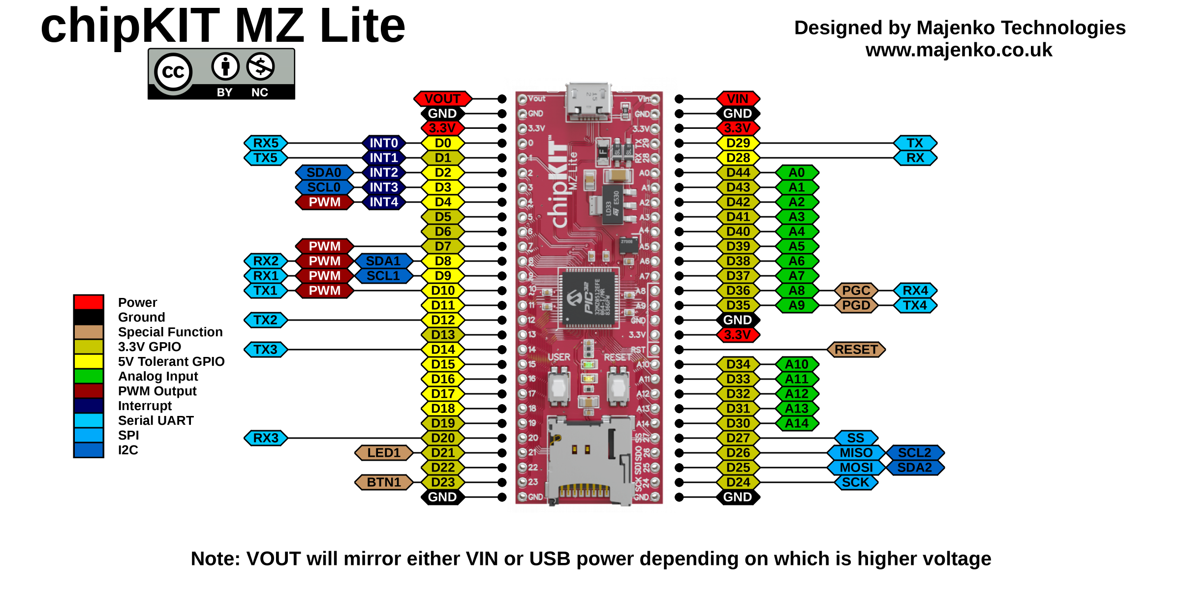
Useful Board Pins
Full Pin Layout
LEDs
LED1 is on digital pin 21. Power (ON) LED is on 3.3V power.
Buttons
There is a "USER" button which shares pin 23. It has no external pullup, so to use it enable INPUT_PULLUP for the pin mode.
Analog Inputs
| Analog Input | Digital Pin |
|---|---|
| A0 | 44 |
| A1 | 43 |
| A2 | 42 |
| A3 | 41 |
| A4 | 40 |
| A5 | 39 |
| A6 | 38 |
| A7 | 37 |
| A8 | 36 |
| A9 | 35 |
| A10 | 34 |
| A11 | 33 |
| A12 | 32 |
| A13 | 31 |
| A14 | 30 |
| A15 | 29 |
Serial Objects
| Serial Object | UART | TX Pin | RX Pin |
|---|---|---|---|
| Serial | USB | none | none |
| Serial0 | UART1 | 29 | 28 |
| Serial1 | UART5 | 10 | 9 |
| Serial2 | UART2 | 8 | 12 |
| Serial3 | UART3 | 14 | 20 |
| Serial4 | UART4 | 35 | 36 |
| Serial5 | UART6 | 1 | 0 |
I2C
| I2C Object | Channel | SDA Pin | SCL Pin |
|---|---|---|---|
| DTWI0 / Wire | 1 | 2 | 3 |
| DTWI1 | 3 | 9 | 10 |
| DTWI2 | 4 | 25 | 26 |
SPI
| SPI Object | Channel | MOSI Pin | MISO Pin | SCK Pin |
|---|---|---|---|---|
| DSPI0 / SPI | 2 | 25 | 26 | 24 |
Note: these pins are also shared with the Micro SD card.
Bootloading
When you want to upload a new sketch to the chipKIT MZ Lite, you need to put it into bootloader mode. This is done by simply tapping the RESET button.
The LED should start pulsating to indicate the bootloader is running. After 15 seconds of inactivity the bootloader exits and returns to normal running mode.
USB Device
The chipKIT MZ Lite has a native USB interface. This allows it to appear as a number of different devices to the computer, including:
- USB Serial Interface (CDC/ACM)
- Keyboard
- Mouse
- Joystick
- MIDI Interface
- Raw HID
FAQ
The computer doesn't detect my chipKIT MZ Lite when it's plugged in. Is it broken?
No, it's not broken. The USB interface is only active when either the bootloader is running or your sketch has specifically requested that it be used through the use of, for example, "Serial.begin(115200);". If your sketch (such as the default Blink sketch) doesn't use the USB interface then the computer won't see the board at all. Pressing the RESET button will enter the bootloader and the computer should then see the board as a custom HID device.