Last edit: 2021-03-21 22:34 by Majenko
ChipKIT MX3
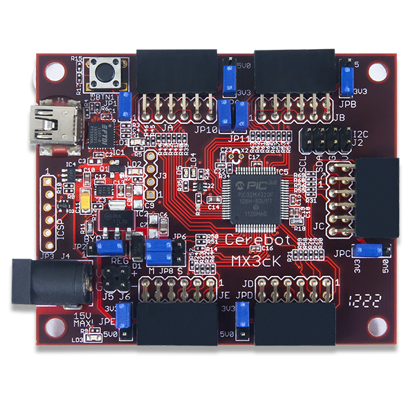
The chipKIT MX3 by Digilent is a microcontroller development board based on the PIC32MX320F128H MCU. It is compatible with Digilent`s line of Pmod™ peripheral modules, and is suitable for use with the MPLAB® IDE and PICkit programmers. The chipKIT MX3 is also compatible with the chipKIT-core™ development environment and Arduino IDE for compatibility with existing code examples, tutorials and resources.
-
The Board Design
-
Useful Board Pins
-
LEDs
-
Analog Inputs
-
Serial Objects
-
I2C
-
SPI
-
Pinout Table
¶The Board Design
- PIC32MX320F128H MCU
- 128K Flash, 16K RAM
- 80 MHz maxixmum operating speed
- 42 I/O pins
- 12 analog inputs
- 5 12-Pin Pmod Ports
- Five PWM outputs and five external interrupt inputs
¶Useful Board Pins
¶LEDs
| LED Name |
Description |
| LD1 |
USB TX Activity LED |
| LD2 |
USB RX Activity LED |
| LD3 |
3.3V Power Supply |
| LD4 |
Digital pin 42 |
| LD5 |
Digital pin 43 |
¶Analog Inputs
| Analog Input |
Digital Pin |
| A0 |
16 |
| A1 |
19 |
| A2 |
20 |
| A3 |
21 |
| A4 |
24 |
| A5 |
27 |
| A6 |
28 |
| A7 |
31 |
| A8 |
37 |
| A9 |
38 |
| A10 |
39 |
¶Serial Objects
| Serial Object |
UART |
TX Pin |
RX Pin |
| Serial |
USB/UART4 |
9 (JB-02) |
10 (JB-03) |
| Serial1 |
UART2 |
17 (JC-02) |
18 (JC-03) |
¶I2C
| I2C Object |
Channel |
SDA Pin |
SCL Pin |
| DTWI0 / Wire |
1 |
SDA1 (40) |
SCL1 (41) |
| DTWI1 |
2 |
SDA2 (18) |
SCL2 (17) |
¶SPI
| SPI Object |
Channel |
SS |
MOSI Pin |
MISO Pin |
SCK Pin |
| DSPI0 / SPI |
1 |
32 |
33 |
34 |
35 |
| DSPI1 |
2 |
8 |
9 |
10 |
11 |
¶Pinout Table
| PIC32 Pin # |
Connector Pin # |
chipKIT Pin # |
PIC32 Signal |
Notes |
| 1 |
JA-08 |
5 |
PMD5/RE5 |
|
| 2 |
JA-09 |
6 |
PMD6/RE6 |
|
| 3 |
JA-10 |
7 |
PMD7/RE7 |
|
| 4 |
JE-04 |
35 |
SCK2/PMA5/CN8/RG6 |
|
| 5 |
JE-03 |
34 |
SDI2/PMA5/CN9/RG7 |
JP6 in M position |
| 6 |
JE-02 |
33 |
SDO2/PMA3/CN10/RG8 |
JP8 in M position |
| 7 |
N/A |
N/A |
MCLR |
|
| 8 |
JE-01 |
32 |
SS2/PMA2/CN11/RG9 |
|
| 9 |
N/A |
N/A |
VSS |
|
| 10 |
N/A |
N/A |
VDD |
|
| 11 |
JE-08 |
37 |
C1IN+/AN5/CN7/RB5 |
A8 |
| 12 |
JE-09 |
38 |
C1IN-/AN4/CN6/RB4 |
A9 |
| 13 |
JE-10 |
39 |
C2IN+/AN3/CN5/RB3 |
A10 |
| 14 |
JD-01 |
24 |
C2IN-/AN2/SS1/CN4/RB2 |
A4 |
| 15 |
JC-08 |
21 |
PGC1/AN1/VREF-/CVREF-/CN3/RB1 |
A3 |
| 16 |
JC-07 |
20 |
PGED1/PMA6/AN0/VREF+/CVREF+/CN2/RB0 |
A2 |
| 17 |
N/A |
N/A |
PGEC2/AN8/OCFA/RB6 |
|
| 18 |
N/A |
N/A |
PGED2/AN7/RB7 |
|
| 19 |
N/A |
N/A |
AVDD |
|
| 20 |
N/A |
N/A |
AVSS |
|
| 21 |
JC-01 |
16 |
U2CTS/C1OUT/AN8/RB8 |
A0 |
| 22 |
JD-04 |
27 |
PMA7/C2OUT/AN9/RB9 |
A5 |
| 23 |
N/C |
N/C |
TMS/CVREFOUT/PMA13/AN10/RB10 |
|
| 24 |
N/C |
N/C |
TDO/PMA12/AN11/RB11 |
|
| 25 |
N/A |
N/A |
VSS |
|
| 26 |
N/A |
N/A |
VDD |
|
| 27 |
JD-07 |
28 |
TCK/PMA11/AN12/RB12 |
A6 |
| 28 |
JD-10 |
31 |
TDI/PMA10/AN13/RB13 |
A7 |
| 29 |
JC-04 |
19 |
PMALH/PMA1/U2RTS/AN14/RB14 |
A1 |
| 30 |
N/C |
N/C |
PMALL/PMA0/AN15/OCFB/CN12/RB15 |
|
| 31 |
JC-03 |
18 |
PMA9/U2RX/SDA2/CN17/RF4 |
|
| 32 |
JC-02 |
17 |
PMA8/U2TX/SCL2/CN18/RF5 |
|
| 33 |
JB-02 |
9 |
U1TX/SDO1/RF3 |
|
| 34 |
JB-03 |
10 |
U1RX/SDI1/RF2 |
|
| 35 |
JB-04 |
11 |
U1RTS/BCLK1/SCK1/INT0/RF6 |
|
| 36 |
J2-3,J2-4 |
40 |
SDA1/RG3 |
|
| 37 |
J2-1,J2-2 |
41 |
SCL1/RG2 |
|
| 38 |
N/A |
N/A |
VDD |
|
| 39 |
N/A |
N/A |
OSC1/CLKI/RC12 |
X1, system clock oscillator |
| 40 |
N/A |
N/A |
OSC2/CLKO/RC15 |
X1, system clock oscillator |
| 41 |
N/A |
N/A |
VSS |
|
| 42 |
JE-07 |
36 |
IC1/RTCC/INT1/RD8 |
|
| 43 |
JB-01 |
8 |
IC2/U1CTS/INT2/RD9 |
|
| 44 |
JD-03 |
26 |
IC3/PMCS2/PMA15/INT3/RD10 |
|
| 45 |
JD-09 |
30 |
IC4/PMCS1/PMA14/INT4/RD11 |
|
| 46 |
JC-09 |
22 |
OC1/RD0 |
PIN_OC1 |
| 47 |
N/A |
N/A |
SOSCI/CN1/RC13 |
X2, secondary oscillator |
| 48 |
N/A |
N/A |
SOSCO/T1CK/CN0/RC14 |
X2, secondary oscillator |
| 49 |
JC-10 |
23 |
OC2/RD1 |
PIN_OC2 |
| 50 |
JD-02 |
25 |
OC3/RD2 |
PIN_OC3 |
| 51 |
JD-08 |
29 |
OC4/RD3 |
PIN_OC4 |
| 52 |
JB-09 |
14 |
PMWR/OC5/IC5/CN13/RD4 |
PIN_OC5 |
| 53 |
JB-08 |
13 |
PMRD/CN14/RD5 |
|
| 54 |
JB-07 |
12 |
CN15/RD6 |
|
| 55 |
JB-10 |
15 |
CN16/RD7 |
|
| 56 |
N/A |
N/A |
VCAP/VDDcore |
|
| 57 |
N/A |
N/A |
ENVREG |
|
| 58 |
N/A |
42 |
RF0 |
PIN_LED1, (LD4) |
| 59 |
N/A |
43 |
RF1 |
PIN_LED2, (LD5) |
| 60 |
JA-01 |
0 |
PMD0/RE0 |
|
| 61 |
JA-02 |
1 |
PMD1/RE1 |
|
| 62 |
JA-03 |
2 |
PMD2/RE2 |
|
| 63 |
JA-04 |
3 |
PMD3/RE3 |
|
| 64 |
JA-07 |
4 |
PMD4/RE4 |
|