chipKIT® Development Platform
Inspired by Arduino™
- Get Started
- Learning
- Products
- Blog
- Beginner
For first time users of chipKIT modules. - Intermediate
For users who have a moderate exposure with chipKIT modules. - Advanced
For users who are experts with chipKIT modules. - Developers
- About Us
- Support
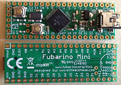
ChipKIT Fubarino Mini
| chipKIT Fubarino Mini | |
|---|---|
 | |
| Specifications | |
| Controller | PIC32MX250F128D-50 |
| Flash | 128KB |
| SRAM | 32KKB |
| Speed | 48MHz |
| Information | |
| Board Define | _BOARD_FUBARINO_MINI_ |
| Links | |
| Designer | Schmalz Haus LLC |
| Product Page | fubarino.org |
| User Guide | FubarinoMiniUserRefManual.pdf |
| Schematic | FubarinoMini_v15_sch.pdf |
| Tech Support | chipkit.net/forum |
| Board Files | Github |
| Bootloader HEX | Fubarino-Mini_USB_48MHz.hex |
| Purchase From | Microchip |
The chipKIT Fubarino Mini is a breadboard form factor chipKIT board with a powerful PIC32 processor that can run Arduino sketches. The chipKIT Fubarino Mini uses the built-in USB peripheral of the PIC32 to both bootload new sketches as well as communicate with the PC (over a virtual serial port). The Fubarino Mini is a very small form factor board with a large number of I/O pins.
The Board Design
- PIC32MX250F128D-50I/ML microcontroller, which includes 128KB Flash and 32K RAM
- Supported as development target from within MPIDE
- Max 33 I/O pins (normally 27)
- Pads for 32 KHz crystal
- CPU runs at 48MHz
- USB connector for power, programming, and connection to PC (serial, mass storage, etc.)
- Two buttons: RESET for resetting the board, and PRG for getting into bootloader mode and user application use
- USB bootloader pre-programmed at the factory – no other hardware needed to program board
- Separate ICSP connector – for hardware programming/debugging with PICKit3 or other ICSP programmer (not needed for use with MPIDE environment)
Useful Board Pins
LEDs
USR_LED1 is on digital pin 1.
Power (PWR) LED is on 3.3V power.
Analog Inputs
| Analog Input | Digital Pin |
|---|---|
| A0 | 0 |
| A1 | 3 |
| A2 | 4 |
| A3 | 5 |
| A4 | 6 |
| A5 | 7 |
| A6 | 8 |
| A7 | 9 |
| A8 | 10 |
| A9 | 11 |
| A10 | 12 |
| A11 | 13 |
| A12 | 20 |
Serial Objects
| Serial Object | UART | TX Pin | RX Pin |
|---|---|---|---|
| Serial | USB | none | none |
| Serial0 | UART1 | 17 | 18 |
| Serial1 | UART2 | 26 | 25 |
I2C
I2C SCK pin is Digial 25, and SDA is Digital 26.
SPI
SPI SS is Digital 30, MOSI is Digital 29, MISO is Digital 27, SCK is Digital 4.
Bootloader Button
Bootloader Button (PRG) is on Digital pin 16, and you can use the constant PIN_BTN1 in your sketch to read this button.
Bootloading
When you want to upload a new sketch to the Fubarino SD board, you need to put it into bootloader mode. This is done by holding down the PRG button while pressing and releasing the RST button, then releasing the PRG button. This will reset the Fubarino SD, and engage the bootloader, which will create a virtual serial port over USB, and wait for MPIDE/UECIDE/Arduino to upload a new sketch. You can also trigger the bootloader from within your sketch.