chipKIT® Development Platform
Inspired by Arduino™
- Get Started
- Learning
- Products
- Blog
- Beginner
For first time users of chipKIT modules. - Intermediate
For users who have a moderate exposure with chipKIT modules. - Advanced
For users who are experts with chipKIT modules. - Developers
- About Us
- Support
Last edit: 2021-03-21 22:34 by Majenko
ChipKIT Pi
| chipKIT Pi | |
|---|---|
 | |
| Specifications | |
| Controller | PIC32MX250F128B |
| Flash | 128kB |
| RAM | 32kB |
| Speed | 40 MHz |
| Information | |
| Board Define | _BOARD_CHIPKIT_PI_ |
| Links | |
| Designer | Element14 |
| Product Page | Element14 |
| User Guide | chipKIT Pi Getting Started (PDF) |
| Schematic | chipKIT PI Schematics (ZIP) |
| Tech Support | chipkit.net/forum |
| Bootloader HEX | Bootloader Image (ZIP) |
| Purchase From | Microchip |
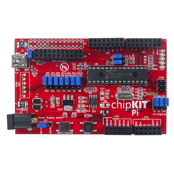
chipKIT™ Pi (Designed for Raspberry Pi) is the latest Arduino™ compatible chipKIT platform from Microchip and element14. It features a 32-bit PIC32 microcontroller in a prototyping-friendly, low pin count SPDIP package. The PIC32s performance, memory and integrated peripherals allow users to create applications including touch sensing, audio processing and advanced control. The board is supported by the free chipKIT Multi-Platform IDE MPIDE that can be hosted on the Raspberry Pi.
The Board Design
- PIC32MX250F128B MCU
- 128K Flash, 32K RAM
- 40 MHz maxixmum operating speed
- 19 I/O pins
- 10 Analog inputs
- Designed exclusively for the Raspberry Pi and chipKIT ecosystem
- Enables the development of 3.3V chipKIT compatible applications for the Raspberry Pi using PIC32 MCU
Useful Board Pins
LEDs
| LED Name | Description |
|---|---|
| LED1 | Digital pin 14 |
| LD2 | Digital pin 15 |
| LD3 | 3.3V Power Supply |
| RX1 | Digital pin 12 |
| TX1 | Digital pin 11 |
Analog Inputs
| Analog Input | Digital Pin |
|---|---|
| A0 | 14 |
| A1 | 15 |
| A4 | 16 |
| A5 | 17 |
Serial Objects
| Serial Object | UART | TX Pin | RX Pin |
|---|---|---|---|
| Serial | USB/UART4 | 1 | 0 |
| Serial1 | UART2 | 5 | 4 |
I2C
| I2C Object | Channel | SDA Pin | SCL Pin |
|---|---|---|---|
| DTWI0 / Wire | 1 | SDA1 (16) | SCL1 (17) |
| DTWI1 | 2 | SDA2 (18) | SCL2 (12) |
SPI
| SPI Object | Channel | SS | MOSI Pin | MISO Pin | SCK Pin |
|---|---|---|---|---|---|
| DSPI0 / SPI | 1 | 10 | 12 | 11 | 13 |
| DSPI1 | 2 |
Pinout Table
| PIC32 Pin # | Connector Pin # | chipKIT Pin # | PIC32 Signal | Notes |
|---|---|---|---|---|
| 1 | - | - | MCLR | Reset |
| 2 | JA3-11 | 14/A0 | PGED3/VREF+/CVREF+/AN0/C3INC/RPA0/CTED1/PMD7/RA0 | |
| 3 | JA1-7 | 11 | PGEC3/VREF-/CVREF-/AN1/RPA1/CTED2/PMD6/RA1 | |
| 4 | JA2-11 | 5/TX2 | PGED1/AN2/C1IND/C2INB/C3IND/RPB0/PMD0/RB0 | |
| 5 | JA2-9 | 4/RX2 | PGEC1/AN3/C1INC/C2INA/RPB1/CTED12/PMD1/RB1 | |
| 6 | JA3-3 | 16/A4/SDA2 | AN4/C1INB/C2IND/RPB2/SDA2/CTED13/PMD2/RB2 | |
| 7 | JA3-1 | 17/A5/SCL2 | AN5/C1INA/C2INC/RTCC/RPB3/SCL2/PMWR/RB3 | |
| 8 | JA4-3, JA4-5 | Ground | VSS | |
| 9 | - | - | OSC1/CLKI/RPA2/RA2 | 8Mhz OSC1 |
| 10 | - | - | OSC2/CLKO/RPA3/PMA0/RA3 | 8Mhz OSC2 |
| 11 | JA1-7 | 11/TX1 | SOSCI/RPB4/RB4 | |
| 12 | 12/RX1 | SOSCO/RPA4/T1CK/CTED9/PMA1/RA4 | ||
| 13 | JA4-9 | 3V3 | VDD | |
| 14 | JA2-5 | 2 | TMS/RPB5/USBID/RB5 | |
| 15 | - | - | VBUS | |
| 16 | JA1-5 | 10 | TDI/RPB7/CTED3/PMD5/INT0/RB7 | |
| 17 | JA1-12 | 12/SCL1 | TCK/RPB8/SCL1/CTED10/PMD4/RB8 | |
| 18 | JA3-3 | 18/SDA1/INT | TDO/RPB9/SDA1/CTED4/PMD3/RB9 | |
| 19 | - | GND | VSS | |
| 20 | - | - | VCAP | |
| 21 | JA1-1 | USB D+/D8 | PGED2/RPB10/D+/CTED11/RB10 | Selected with JP13 |
| 22 | JA1-3 | USB D-/PWM1 | PGEC2/RPB11/D-/RB11 | Selected with JP12 |
| 23 | - | - | VUSB3V3 | |
| 24 | JA2-7 | 3 | AN11/RPB13/CTPLS/PMRD/RB13 | |
| 25 | JA1-11 | 13 | CVREFOUT/AN10/C3INB/RPB14/VBUSON/SCK1/CTED5/RB14 | |
| 26 | JA3-9 | 15/A1 | AN9/C3INA/RPB15/SCK2/CTED6/PMCS1/RB15 | |
| 27 | - | - | AVSS | |
| 28 | - | - | AVDD |