chipKIT® Development Platform
Inspired by Arduino™
- Get Started
- Learning
- Products
- Blog
- Beginner
For first time users of chipKIT modules. - Intermediate
For users who have a moderate exposure with chipKIT modules. - Advanced
For users who are experts with chipKIT modules. - Developers
- About Us
- Support
Basic IO Shield
Basic I/O Shield
The Basic IO Shield is a powerful tool for rapid development of prototypes on the chipKIT platform. As you may know chipKIT has evolved over time and several development environments exist which support the chipKIT core. The tutorials on this page will focus on getting the Basic I/O Shield working with a uC32 in the Arduino IDE.
{{:How-To Install chipKIT Core}}
Installing Basic I/O Libraries
chipKIT Third Party Libraries Downloads
Download all the Third Party Libraries (zip)]. Note that this may also include libraries you don't intend to use. If you wish to only download the libraries you need then visit [https://github.com/chipKIT32/thirdpartylibraries [https://github.com/chipKIT32/thirdpartylibraries].
Windows Installation
If you are following along carefully you should know your sketchbook location. If not then navigate to File -> Preferences and find the location at the top of the dialog. It should be something like C:\Users\BaltimoreHackerspace\OneDrive\Documents\Arduino. Inside this folder should be a libraries folder. If one does not exist you will need to create it. Then extract the following folders into the libraries directory:
IOShieldEEPROM
: This Library makes use of the existing Wire library to communicate with the EEPROM on the IOShield.
IOShieldOled
: This Library allows you to write to the OLED screen on the Basic I/O Shield.
IOShieldTemp
: This Library provide necessary functions to interface with the on board temperature sensor on the Basic I/o Shield .
chipKIT Board Configuration
uC32
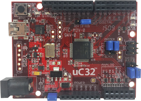 The Basic I/O Shield uses an SPI2 interface to communicate with the OLED display. Therefore, the JP4 jumper (pin 10) has to be routed to the SS2/RG9 net by placing the jumper in the RG9 position. The SPI Jumpers JP5 and JP7 should be in the MASTER position. Also, JP6 and JP8 should be placed in the RG3 and RG2 positions respectively in order to route the I2C lines to the Temperature Sensor and EEPROM on the Basic I/O Shield.
Jumper Settings
| Jumper | Position | Net Name | Function |
|---|---|---|---|
| JP4 | RG9 | SS2//RG9 | SPI Signal Select |
| JP5 | MASTER | SDI2/RG7 | SPI Data Input |
| JP7 | MASTER | SDO2//RG8 | SPI Data Output |
| JP6 | RG3 | SDA1/RG3 | I2C Data |
| JP8 | RG2 | SCL1/RG2 | I2C Clock |
Examples
Inside each of the libraries folders is a folder called examples. These folders contain the following examples: