chipKIT® Development Platform
Inspired by Arduino™
- Get Started
- Learning
- Products
- Blog
- Beginner
For first time users of chipKIT modules. - Intermediate
For users who have a moderate exposure with chipKIT modules. - Advanced
For users who are experts with chipKIT modules. - Developers
- About Us
- Support
Basic BLE
Introduction
A Tutorial on Connecting a ChipKIT Board to a Phone App via BLE
Microchip has a number of Bluetooth modules, including ones that use BLE to communicate with smart phones. In this tutorial, we will use a RN4871 Bluetooth module from Microchip, connected to a chipKIT Fubarino Mini board. (Any chipKIT board will work just fine, as should any Arduino or Arduino-compatible, like a Teensy or Feather, etc.) We will use an app that Microchip has written called the BLE Sensor App, which is available for both iPhone and Android. We will use a BLE library from within the Arduino IDE, and load a sketch onto the Fubarino Mini that will allow it to control parts of the phone app, and be controlled by the phone app as well, all over BLE.
Here is what these two modules (RN4870 and RN4871) look like:
file:RN4870.PNG file:RN4871.PNG
Along the way, we will discuss some of the necessary topics used in BLE, as well as how the RN478x implements BLE commands.
None of this tutorial other than the RN4781 pin numbers is specific to the RN4871 - you can use an RN4870 just as well. (And in fact the RN4870 has better radio range.)
A reminder: Bluetooth, and BLE specifically, is quite complicated. (It is rightly criticized for being overly so.) There are lots of good places around the web to learn about all of the various details of BLE. In this tutorial, we will only briefly touch on basic BLE concepts except where necessary to understand specific nuances of the code or explain comments in the sketch.
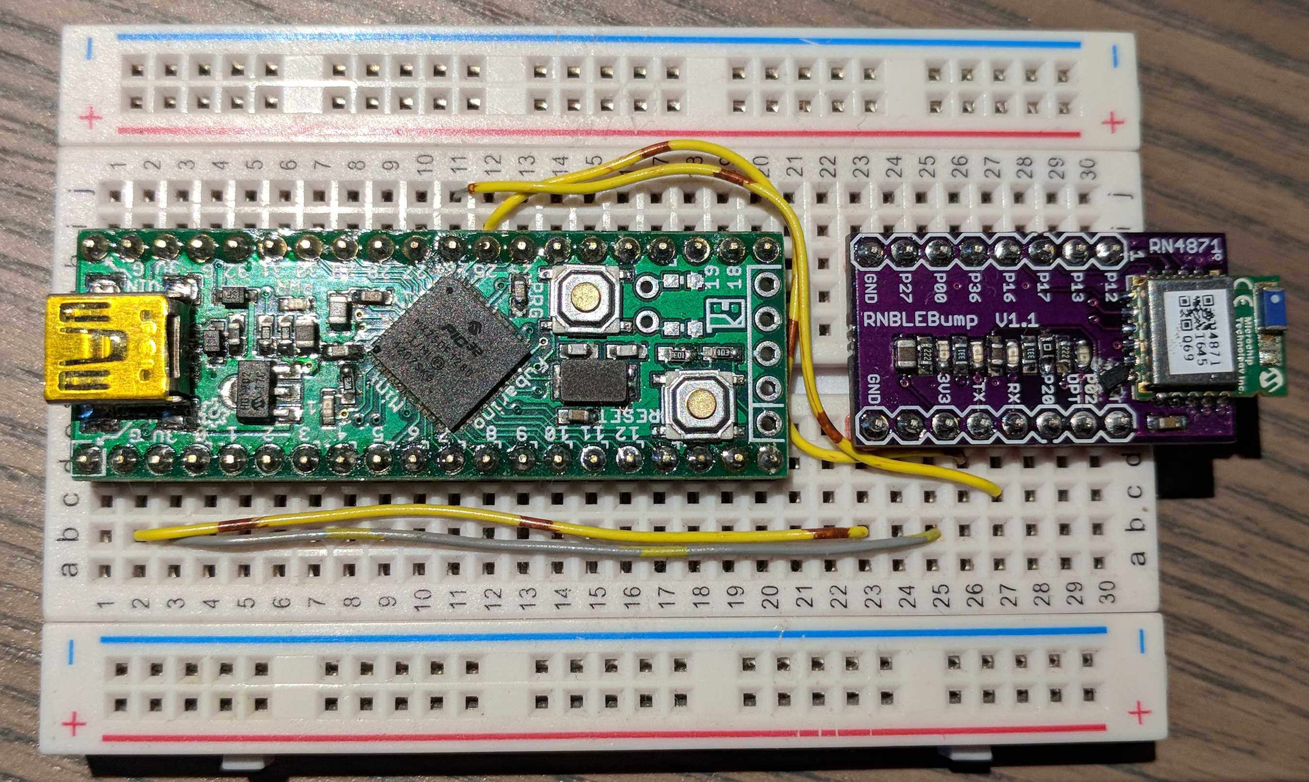
Hardware Setup
This diagram shows all of the major parts of the system used for this tutorial.

-
The Fubarino Mini chipKIT board gets power (and is programmed) by a USB connection to a PC, although no PC software needs to be running while the system is operating.
-
The RN4871 BLE Module is mounted to a small breakout board
-
Both Fubarino Mini and RN4871 are mounted to a breadboard, and power, ground, TX and RX are connected between them
-
A mobile device (tablet/phone) is loaded with Microchip's BLE Sensor App
-
The Fubarino Mini is loaded with the sketch as listed below, to send/receive data from the app on the phone over BLE
-
The PRG button and LED on the Fubarino Mini are mapped to the "switch" and "LED" controls on the mobile device
Here is one way of connecting up the Fubarino Mini and RN4871. Note that an RNN4870 can also be used, but its pinout is different. We've used a small breakout board for the BLE module so that it will fit into a breadboard.
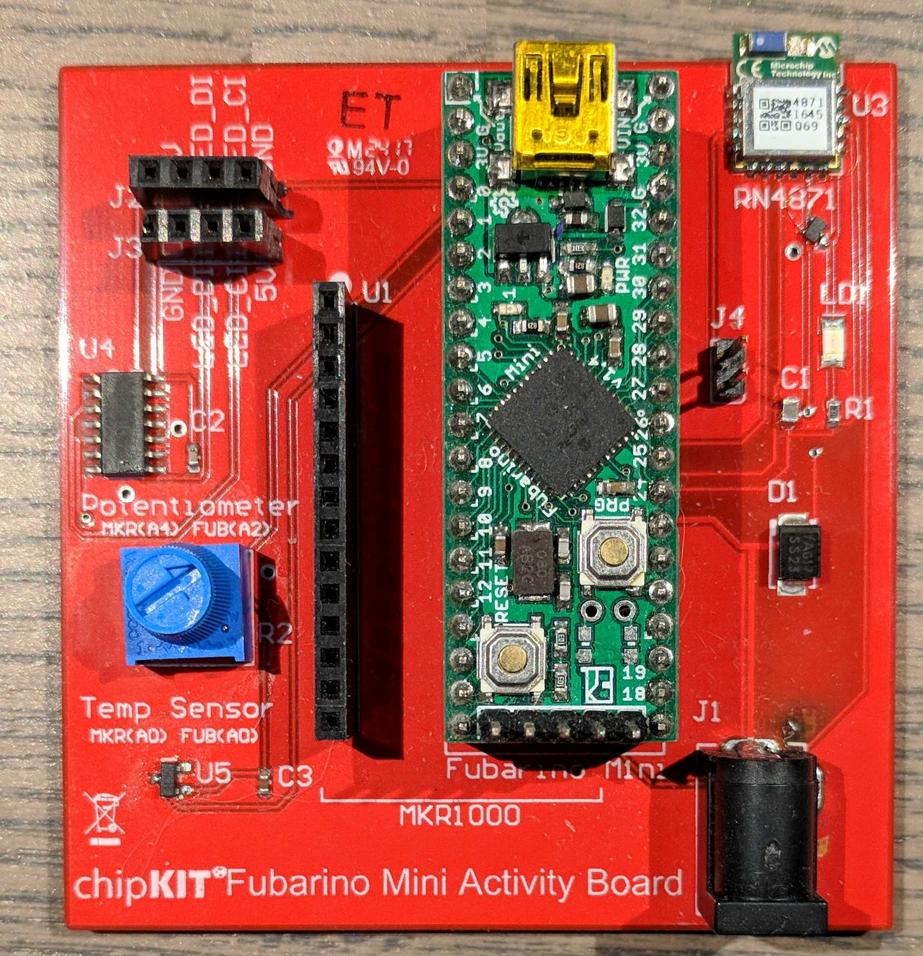
The chipKIT Fubarino Mini Activity Board (Used for both chipKIT classes at Microchip MASTERs 2017) is also set up to work perfectly with this tutorial. The temperature sensor and potentiometer on the Activity Board connect up with the temperature and potentiometer controls in the BLE Sensor App.
- Important Note: The current RN487x modules need external reset controller chips to guarantee that their internal flash does not become corrupted on power up or power down. In the above picture, you can see a Microchip MCP121T-315E/TT reset controller chip soldered onto the breakout board.
Software Setup
There are two pieces of software required for this tutorial. The first is the Arduino sketch (or embedded application) that runs on the Fubarino Mini chipKIT board. The second is the mobile application running on a mobile device.
RN487x Library Overview
The RN487x BLE module communicates with a microcontroller via a standard 2-wire asynchronous serial (i.e. UART) channel. The BLE module normally passes data through from the UART to the BLE interface. This is called "Data Mode". The library does not make use of Data Mode. Rather, the library places the module into "Command Mode", where data sent over the UART channel is interpreted by the module as commands for it.
The BLE module has several advanced features (like remote command console and transparent UART mode) which are not yet supported by the library. Instead, the library provides a C-friendly way to execute all of the common commands - primarily dealing with configuration of the BLE module.
The BLE module's Command Mode takes simple ASCII strings (i.e. 'commands') from the microcontroller, executes each command, and returns an ASCII string as a reply back to the microcontroller. The BLE library knows what replies are appropriate for each command, and after sending a given command, waits for the appropriate response from the BLE module before continuing on. In other words, each of the BLE library function calls blocks until the module has received the command, executed it, and responded. There is also a timeout mechanism if the module does not respond appropriately in a given amount of time.
The BLE module currently consists primarily of wrapper function calls, where each function call prepares and sends a single command to the BLE module. In your sketch, you will need to sequence each of the function calls as necessary to set up the BLE module for your project. To understand which commands needs to be send, and thus how to use the library, you will need to understand the RN4870-71 Users Guide.
Not every BLE module command has a library equivalent yet, but all of the critical commands are represented in the library. Future updates to the library will include more and more of the module's commands.
For example, the getConnectionStatus() function sends the "GK" command to the BLE module. This command queries the module for the current BLE connection status. The module then sends back a response, the library waits for it, and returns true or false to your sketch depending on if there is an active BLE connection or not.
Arduino Sketch
The sketch code is copied below. It is also available in the examples section once the RN487x library is installed in your Arduino IDE.
You will need to install the Arduino IDE, the chipKIT-core, and the RN487x library in order to compile this sketch.
Installing Sketch Software
Get this tutorial sketch running, follow these instructions:
Follow these instructions to install the Arduino IDE and chipKIT-core inside the IDE : How-To Install chipKIT Core
Install the RN487x library by
Go to the Sketch->Include Library->Manage Libraries menu to get to the Library Manager
Type in RN487x in the search box (upper right hand corner of the Library Manger window)
Make sure to install version 1.1.1 or above of the library
Click on the "Install" button to install the library
Open up the BLE sensor sketch. You can copy/paste this into your Arduino IDE, or select it from the Examples->Examples From Custom Libraries->RN487x->BLE_SensorApp menu.
If you want to install the library manually for any reason, the library is located here : github.com/chipKIT32-libraries/RN487x
Sketch Code : Overview
There are five main sections of the sketch:
-
Includes and Defines
This section simply sets up the libraries that are used in the sketch, the names of the two serial ports used, and the pin defines for the two analog inputs. -
Global Variables
This section defines each of the variables that holds the information about each piece of data sent/received over BLE -
Helper Functions
These two little functions read and scale the two analog input values for use on the mobile app -
Setup
This section clears out the BLE module's settings, and configures it for the sketch's use. All of the various pieces of data to be sent/received are defined, as well as advertisement data, etc. -
Loop
This is the main section of the sketch. It runs over and over and checks to see if a mobile device has connected to the BLE module, and if so, it sends out each of the 5 pieces of data and receives the LED data from the mobile app.
Full Sketch Source Code
#include <Arduino.h>
#include <RN487x_BLE.h>
#include <SoftPWMServo.h>

#define debugSerial Serial
#define bleSerial Serial1

#define BLUETOOTH_WAKE      12
#define BT_RESET             7

/* Analog pin that temp sensor is connected to */
#define TEMP_SENSOR A0
/* Analog pin that pot is connected to */
#define POT_SENSOR A2
/* Maximuim number of milliseconds to wait for USB serial to get ready on boot */
#define SERIAL_TIMEOUT_MS  5000

const char* myDeviceName = "FB Mini";  // Custom Device name
const char* myPrivateServiceUUID = "AD11CF40063F11E5BE3E0002A5D5C51B"; // Custom private service UUID

// Light Sensor
const char* lightCharacteristicUUID = "BF3FBD80063F11E59E690002A5D5C501";  // custom characteristic GATT
const uint8_t lightCharacteristicLen = 2;  // data length (in bytes)
const uint16_t lightHandle = 0x72;
char lightPayload[lightCharacteristicLen*2 + 1];

// Pot
const char* potCharacteristicUUID = "BF3FBD80063F11E59E690002A5D5C502";  // custom characteristic GATT
const uint8_t potCharacteristicLen = 2;  // data length (in bytes)
const uint16_t potHandle = 0x75;
char potPayload[potCharacteristicLen*2 + 1];

// Switch/LED
const char* switchCharacteristicUUID = "BF3FBD80063F11E59E690002A5D5C503";  // custom characteristic GATT
const uint8_t switchCharacteristicLen = 20;  // data length (in bytes)
const uint16_t switchHandle = 0x78;
char switchPayload[switchCharacteristicLen*2 + 1];
const char* ledPayload;

// Temp
const char* temperatureCharacteristicUUID = "BF3FBD80063F11E59E690002A5D5C504";  // custom characteristic GATT
const uint8_t temperatureCharacteristicLen = 2;  // data length (in bytes)
const uint16_t temperatureHandle = 0x7B;
char temperaturePayload[temperatureCharacteristicLen*2 + 1];

// Battery
const char* batteryCharacteristicUUID = "BF3FBD80063F11E59E690002A5D5C505";  // custom characteristic GATT
const uint8_t batteryCharacteristicLen = 2;  // data length (in bytes)
const uint16_t batteryHandle = 0x7E;
char batteryPayload[batteryCharacteristicLen*2 + 1];


/**
 * Read Activity Board temperature sensor in degrees C
 */
float getTemperature()
{
  float accumulator = 0;

  // Make 1000 analog conversions
  for (int i=0; i < 1000; i++)
  {
    float sensorValue = analogRead(TEMP_SENSOR);

    // Convert them to raw volts (raw ADC is 0 to 1023), added fudge factor for accuracy
    float voltage = (sensorValue * (3.3 / 1024.0)) + 0.0025;

    // Sum the raw volts value into the accumulator
    accumulator += voltage;
  }

  // Compute the average voltage over all conversions
  float volt_ave = accumulator/1000.0;

  // Compute Celsius. Sensor reads in 10mV/deg C, with 500mV offset
  float celsius = ((volt_ave * 1000.0) - 500.0) / 10.0;

  return (celsius);
}

/**
 *  Read pot in milivolts
 */
int getPot()
{
  return ((analogRead(POT_SENSOR) * 3.3) / 1.023);
}

void setup()
{

  debugSerial.begin(115200);

  // Wait for PC to connect, give up after SERIAL_TIMEOUT_MS
  while ((!debugSerial) && (millis() < SERIAL_TIMEOUT_MS));

  // Set the optional debug stream
  rn487xBle.setDiag(debugSerial);
  // Initialize the BLE hardware with our sleep and wakeup pins
  rn487xBle.hwInit(BT_RESET, BLUETOOTH_WAKE);
  // Open the communication pipe with the BLE module
  bleSerial.begin(rn487xBle.getDefaultBaudRate());
  // Assign the BLE serial port to the BLE library
  rn487xBle.initBleStream(&bleSerial);
  // Finalize the init. process
  if (rn487xBle.swInit())
  {
    debugSerial.println("Init. procedure done!");
  }
  else
  {
    debugSerial.println("Init. procedure failed!");
    while(1);
  }

  // Fist, enter into command mode
  rn487xBle.enterCommandMode();
  // Stop advertising before starting the demo
  rn487xBle.stopAdvertising();
  rn487xBle.clearPermanentAdvertising();
  rn487xBle.clearPermanentBeacon();
  rn487xBle.clearImmediateAdvertising();
  rn487xBle.clearImmediateBeacon();
  rn487xBle.clearAllServices();
  // Set the serialized device name
  rn487xBle.setSerializedName(myDeviceName);
  rn487xBle.setSupportedFeatures(0x4000); // Set to no prompt (no "CMD>")
  rn487xBle.setDefaultServices(DEVICE_INFO_SERVICE);
  // Set the advertising output power (range: min = 5, max = 0)
  rn487xBle.setAdvPower(3);
  rn487xBle.reboot();
  rn487xBle.enterCommandMode();
  rn487xBle.clearAllServices();
  // Set a private service ...
  rn487xBle.setServiceUUID(myPrivateServiceUUID);
  // which contains ...
  // ...a light sensor (unused) characteristic; readable and can perform notification, 2-octets size
  rn487xBle.setCharactUUID(lightCharacteristicUUID, NOTIFY_PROPERTY, lightCharacteristicLen);
  // ...a pot characteristic; readable and can perform notification, 2-octets size
  rn487xBle.setCharactUUID(potCharacteristicUUID, NOTIFY_PROPERTY, potCharacteristicLen);
  // ...a LED/Switch characteristic; readable and can perform notification, 20-octets size
  rn487xBle.setCharactUUID(switchCharacteristicUUID, WRITE_PROPERTY | NOTIFY_PROPERTY, switchCharacteristicLen);
  // ...a temperature characteristic; readable and can perform notification, 2-octets size
  rn487xBle.setCharactUUID(temperatureCharacteristicUUID, NOTIFY_PROPERTY, temperatureCharacteristicLen);
  // ...a battery (unused) characteristic; readable and can perform notification, 2-octets size
  rn487xBle.setCharactUUID(batteryCharacteristicUUID, NOTIFY_PROPERTY, batteryCharacteristicLen);

  rn487xBle.startPermanentAdvertising(AD_TYPE_FLAGS, "06");
  rn487xBle.startPermanentAdvertising(AD_TYPE_MANUFACTURE_SPECIFIC_DATA, "CD00FE14AD11CF40063F11E5BE3E0002A5D5C51B");

  // take into account the settings by issuing a reboot
  rn487xBle.reboot();
  rn487xBle.enterCommandMode();

  rn487xBle.startCustomAdvertising(210);

  debugSerial.println("Fubarino Mini Activity Board as a Peripheral with private service");
  debugSerial.println("================================================");
  debugSerial.println("You can now establish a connection from the Microchip SmartDiscovery App");
  debugSerial.print("with the board: ") ; debugSerial.println(rn487xBle.getDeviceName());
}

void loop()
{
  // Check the connection status
  if (rn487xBle.getConnectionStatus())
  {
    // We are connected to a peer
    debugSerial.print("Connected to a peer central ");
    debugSerial.println(rn487xBle.getLastResponse());

    // Light Sensor
    // 1000d = 21 lux
    // 2000d = 83 lux
    // Since we don't have a light sensor, just hard-code this to a known value
    sprintf(lightPayload, "%04X", 2000);
    rn487xBle.writeLocalCharacteristic(lightHandle, lightPayload);

    // Temperature
    /* Convert to units that the Phone app wants
     * 1000d = -8.47 F (Apple) --- (Android)
     * 1200d = 18.29 F (Apple) 39.76 F (Android)
     * 1500d = 58.84 F (Apple) 85.24 F (Android)
     * 1600d = 71.8 F (Apple)
     * So to convert from Celcius to counts that the app needs, we mulitply by 13.32 and add 1302 (for Apple)
     * Note that the two phone apps interpret this value differently, so we can't create one formula that will
     * work properly for both. This math is set up for the iPhone app.
     */
    sprintf(temperaturePayload, "%04X", (uint16_t)((getTemperature() * 13.32) + 1302.0));
    rn487xBle.writeLocalCharacteristic(temperatureHandle, temperaturePayload);

    // Pot
    sprintf(potPayload, "%04X", getPot());
    rn487xBle.writeLocalCharacteristic(potHandle, potPayload);

    // Battery
    // 2000 = 7%
    // 3000 = 78%
    // Since we don't have a battery sensor, just hard code this to be a known value
    sprintf(batteryPayload, "%04X", 3000);
    rn487xBle.writeLocalCharacteristic(batteryHandle, batteryPayload);

    // LED
    // This one is the complicated one. Every time the user moves the LED slider on the phone
    // app, the readLocalCharactistic will get a value like XXXXXXXX2CYYYYYYYY where XXXXXXXX
    // and YYYYYYYY are four byte hex numbers encoded as ASCII values. (So 0x89AB would be
    // 38394142) I'm not exactly sure what each value is for, but we just use the first
    // one to dim the LED on the Fubarino.
    if (rn487xBle.readLocalCharacteristic(switchHandle))
    {
      ledPayload = rn487xBle.getLastResponse();
      if ((ledPayload != NULL) && (ledPayload[0] != 'N') && (strlen(ledPayload) >= 9)) // != "N/A" response
      {
        // The difficult thing here is that beacuse the value is encoded as ASCII values, we have
        // to convert each of the 4 ASCII values into the 4 hex bytes, then interpret the hex
        // value as a number. Also, for some reason "%2hhx" doesn't seem to work in this version
        // of sscanf, so we can't directly convert the ASCII values into bytes, we have to have
        // sscanf convert each 2-byte ASCII value into an int, then cast that into to a byte.
        // Then the resulting four byte string can be converted to a 16-bit unsigned number.
        // Seems like way too much work to go through just to get a 16 bit value from the phone.
        uint32_t led = 0;
        uint32_t hexstring_int[4];
        uint8_t hexstring[5];
        uint8_t i;

        for (i=0; i < 4; i++)
        {
          sscanf(&ledPayload[i*2], "%2x", (unsigned int *)&hexstring_int[i]);
          hexstring[i] = hexstring_int[i];
        }
        hexstring[4] = 0;

        // led = 500 when slider is all the way right (android) or 1750 (Apple)
        // led = 0 when slider is all the way left (android and Apple)
        // led = 26670 when slider is just a bit in from the left side, decreasing down to 500 on the right side (28221 Apple)
        sscanf((char*)hexstring, "%x", (unsigned int *)&led);
        SoftPWMServoPWMWrite(PIN_LED1, map(led, 28000, 500, 0, 255));
      }
    }

    // Switch
    // Note that because we use the same server characteristic for sending switch data to the phone as well
    // as getting LED information back from the phone, we have to do things in this order (LED read first,
    // then switch write) otherwise the LED read will always return "0001" or "0000" from the switch write.
    sprintf(switchPayload, "000%1d", digitalRead(PIN_BTN1));
    rn487xBle.writeLocalCharacteristic(switchHandle, switchPayload);

    // Delay inter connection polling - when connected, update every 1/4 second
    delay(250);
  }
  else
  {
    // Not connected to a peer device
    debugSerial.println("Not connected to a peer device");

    // Delay inter connection polling - when not connected, check for new connections ever 1 second
    delay(1000);
  }
}
Mobile Apps
There are two versions of the Microchip BLE Sensor App : one for Android, and one for iOS. Simply search in the respective app store (Google Play or Apple App Store) and search for "BLE Sensor App". Make sure you install the one from Microchip, as there may be multiple hits for that search term. The app is free, and should only need access to BLE.
The two applications are actually different, and will interpret the data from the Fubarino Mini in slightly different ways.
Once you have the sketch running properly on the Fubarino Mini, you can start up the mobile application, and it will show you a list of BLE devices that have the proper advertisement payload.
This is what the Android application looks like on this first 'scanner' page:
The iOS version is very similar.
By clicking on the found device (called "Unknown Device" here), the app will actually connect to the RN4871 BLE module and begin transferring data.
300px 1
Running The Demo
Connecting The Board and App
Once you have compiled and uploaded the sketch to the Fubarino Mini board, you can start up the BLE Sensor app on your mobile device. If everything is working, when you start the app you should see a screen that will show a list of all of the BLE devices nearby that are transmitting the correct advertisement packet (most likely only one device - your Fubarino Mini) - this is the "BLE Sensors" screen. If you touch on that device in the list, it will take you to a page called "Sensor Board", which has a "Switch", "LED", "Light Meter", "Potentiometer", "Temperature" and "Battery" sections.
If you press the PRG button on the Fubarino Mini, you will see the light bulb in the "Switch" section of the app go dark.
If you move the LED slider on the app left and right, you will see the green LED on the Fubarino Mini change brightness.
This is showing that two way communication between your sketch and the mobile app is taking place, and is the whole point of this entire thing!
If you let your phone go to sleep, it will disconnect from the RN4871. When you wake it back up, it will reconnect and start sharing data again.
Touching on the back arrow at the top of the screen will take you back to the "BLE Sensors" (i.e. scanner) screen
Serial Output
If you open up the serial port created by the sketch in a terminal emulator on your computer, you'll see the following output when the sketch starts up:
Init. procedure done!
Fubarino Mini Activity Board as a Peripheral with private service
================================================
You can now establish a connection from the Microchip SmartDiscovery App
with the board: FB Mini
At that point, the main loop will start running and you will see this line over and over again as long as nothing has connected to the Fubarino Mini:
Not connected to a peer device</pre>

Once a mobile app connects, you will see the following line (with a different address):

<pre>Connected to a peer central 63DD777520DF,1,0
which repeats once every time through the main loop.
Now, if you want to see a lot more debug output, you can go into the library file RN487x_BLE.cpp, and uncomment the line "//#define DEBUG" near line 31. This file will be located in Arduino\libraries\RN487x\src\RN487x_BLE.cpp. If you then recompile and run the sketch again, you'll get output like this:
[hwInit]
[hwReset skipped]
[wakeUp - skipped]
[swInit]
[reboot]
[sendCommand] R,1
[expectResponse] expecting Rebooting
) found a match !
Init. procedure done!
[enterCommandMode]
[expectResponse] expecting CMD> or CMD
............................................................................................................................................................................................................................................(CMD
) found a match ! - Command prompts are disabled.
[stopAdvertising]
[sendCommand] Y
[expectResponse] expecting AOK
) found a match !
[clearPermanentAdvertising]
[sendCommand] NA,Z
[expectResponse] expecting AOK
) found a match !
[clearPermanentBeacon]
[sendCommand] NB,Z
[expectResponse] expecting AOK
) found a match !
[clearImmediateAdvertising]
[sendCommand] IA,Z
[expectResponse] expecting AOK
) found a match !
[clearImmediateBeacon]
[sendCommand] IB,Z
[expectResponse] expecting AOK
) found a match !
[cleanAllServices]
[sendCommand] PZ
[expectResponse] expecting AOK
) found a match !
[setSerializedName] FB Mini
[sendCommand] S-,FB Mini
[expectResponse] expecting AOK
) found a match !
[setSupportedFeatures][sendCommand] SR,4000
[expectResponse] expecting AOK
) found a match !
[setDefaultServices][sendCommand] SS,80
[expectResponse] expecting AOK
) found a match !
[setAdvPower] 3
[sendCommand] SGA,3
[expectResponse] expecting AOK
) found a match !
[reboot]
[sendCommand] R,1
[expectResponse] expecting Rebooting
) found a match !
[enterCommandMode]
[expectResponse] expecting CMD> or CMD
etc. As you can see, this output mode shows all of the commands that go to the BLE module, and all of the commands that come back, which is very helpful for debugging your sketch.
Sketch Analysis
This section of the tutorial will go through each part of the sketch, and explain how the BLE library is used, and what BLE features are being exercised.
Includes and Defines
#include <Arduino.h>
#include <RN487x_BLE.h>
#include <SoftPWMServo.h>

#define debugSerial Serial
#define bleSerial Serial1

#define BLUETOOTH_WAKE      12
#define BT_RESET             7

/* Analog pin that temp sensor is connected to */
#define TEMP_SENSOR A0
/* Analog pin that pot is connected to */
#define POT_SENSOR A2
/* Maximuim number of milliseconds to wait for USB serial to get ready on boot */
#define SERIAL_TIMEOUT_MS  5000
In this section of the code, the standard Arduino.h header is included, as well as the header for the BLE library (RN487x_BLE.h) and the library which is used to dim the built-in LED on the Fubarino Mini (SoftPWMServo.h).
There are actually two different serial ports used in this sketch - the first is the 'debugSerial' port, which is used to send output messages to the PC so the user can follow along with the progress of the sketch. Notice that this serial port is defined as "Serial", which is the USB port on this chipKIT board.
The second serial port ("bleSerial") is the hardware UART used to communicate with the RN4871 BLE module. On the Fubarino Mini, "Serial1" is the RX2/TX2 pair on pins 25 and 26 respectively.
There are two other connections that this sketch tries to make with the RN487x module - the Wakeup pin and the Reset pin. If you decide to connect to these two pins on your BLE module, edit your copy of the sketch so that the two #define statements contain the Arduino pin numbers you used for the Wakeup and Reset connections. These are optional, and it won't affect the operation of the sketch if you remove these lines (if you don't connection Wakeup and Reset).
The sketch also defines two analog inputs, one for the temp sensor (on analog input A0 - used on the Activity Board), and one for the potentiometer (analog input A2 - again from the Activity Board). You can of course connect other things to these two analog inputs, and their values will show up on the mobile app as "Temperature" and "Potentiometer " values.
The last define in this section is a timeout value for the USB serial (i.e. debug serial) port. If the user does not open the serial port on the PC side in this amount of time (from boot), then the sketch will proceed ahead anyway.
Global Variables
const char* myDeviceName = "FB Mini";  // Custom Device name
const char* myPrivateServiceUUID = "AD11CF40063F11E5BE3E0002A5D5C51B"; // Custom private service UUID

// Light Sensor
const char* lightCharacteristicUUID = "BF3FBD80063F11E59E690002A5D5C501";  // custom characteristic GATT
const uint8_t lightCharacteristicLen = 2;  // data length (in bytes)
const uint16_t lightHandle = 0x72;
char lightPayload[lightCharacteristicLen*2 + 1];

// Pot
const char* potCharacteristicUUID = "BF3FBD80063F11E59E690002A5D5C502";  // custom characteristic GATT
const uint8_t potCharacteristicLen = 2;  // data length (in bytes)
const uint16_t potHandle = 0x75;
char potPayload[potCharacteristicLen*2 + 1];

// Switch/LED
const char* switchCharacteristicUUID = "BF3FBD80063F11E59E690002A5D5C503";  // custom characteristic GATT
const uint8_t switchCharacteristicLen = 20;  // data length (in bytes)
const uint16_t switchHandle = 0x78;
char switchPayload[switchCharacteristicLen*2 + 1];
const char* ledPayload;

// Temp
const char* temperatureCharacteristicUUID = "BF3FBD80063F11E59E690002A5D5C504";  // custom characteristic GATT
const uint8_t temperatureCharacteristicLen = 2;  // data length (in bytes)
const uint16_t temperatureHandle = 0x7B;
char temperaturePayload[temperatureCharacteristicLen*2 + 1];

// Battery
const char* batteryCharacteristicUUID = "BF3FBD80063F11E59E690002A5D5C505";  // custom characteristic GATT
const uint8_t batteryCharacteristicLen = 2;  // data length (in bytes)
const uint16_t batteryHandle = 0x7E;
char batteryPayload[batteryCharacteristicLen*2 + 1];
The first line of this section defines a device name ("FB Mini"), which is something the RN4871 sends out with it's advertisement. That's why it shows up in the 'scanner' list (i.e. first page) of the mobile list. Due to a bug in the Android version of the app, this name only shows up in the iOS version of the app.
Next is a private UUID string, which is used when setting up the services (explained below). UUIDs are 128 bit hexadecimal strings that are supposed to be unique across all BLE devices. They act as a sort of 'name' that both sides can use to refer to a particular piece of information - in this case, a private service UUID. This page contains some more information on the relationship between services and characteristics: learn.adafruit.com/introduction-to-bluetooth-low-energy/gatt
There are five different pieces of information (in BLE parlance they are called 'characteristics') that we will be sending or receiving from the mobile app :
- A Light Sensor value - sent to the Mobile App
- A Potentiometer value - sent to the Mobile App
- A Switch value and LED value - the switch value is an on/off value of the PRG button on the Fubarino Mini and it is sent to the Mobile App, while the LED value is a slider value from the App that is sent down to the chipKIT
- A Temp value - the reading from the temp sensor is sent up to the Mobile App
- A Battery value - sent to the Mobile App
In the next section four variables need to be defined as global variables for each piece of information (characteristic):
A unique "UUID" string (128 bit) value which is used by both BLE module and Mobile App to uniquely give a name to this piece of information ('characteristic')
A data length, in bytes. This is the number of bytes of hexadecimal data in this characteristic. For example, 2 would be 2 bytes of data, which will take up four characters (i.e. "AF34" is the ASCII string representation of the hex number 0xAF34, or 44852 decimal.
A handle. This handle is a 16 bit number which is assigned by the BLE module when you register the characteristic. It is used as a type of reference ID for other commands to refer to this particular characteristic.
Finally the actual string, which holds the ASCII representation of the numeric value of the characteristic. This will always be twice the byte length of the numeric size of the characteristic, plus 1 for the zero byte at the end to make it a real C string.
One very important thing to keep in mind here is that this sketch and the mobile apps are programmed to store all exchanged data as strings of hex values. So, if you want to send the decimal value 1000 to the app for the Temperature characteristic, you would print "03E8" into the temperaturePayload[] array. Notice how temperatureCharacteristicLen is defined as 2 (as in '2 bytes'), because the number that is being sent can range from 0 to 65535. However, this value is stored in a string that needs to be 5 bytes long (four for the four digits of the hexadecimal representation of the number, plus a terminating null), thus the length of temperaturePayload[] is set to temperatureCharacteristicLen*2 + 1.
There is no reason that this system has to be used - you could just as easily used normal integers and not converted to strings, but these two apps are written to expect strings, and so the sketch must provide strings. Keep this in mind when thinking about how data is transferred in the rest of the sketch below.
How does one get the handle value of each characteristic as it is registered with the BLE module? The answer is the 'LS' command. While the library doesn't yet support this command, you can connect to the BLE module directly over serial to your PC (or through the chipKIT board by using a simple serial pass through sketch) and send the 'LS' command after all of the characteristics have been set up. This results in the module sending back a list of all of the characteristics, and the various pieces of data it associates with each one, including the handle numbers.
For example, after all of the setup() is complete, if you were to send the 'LS' command you would get this back:
AD11CF40063F11E5BE3E0002A5D5C51B
  BF3FBD80063F11E59E690002A5D5C501,0072,00
  BF3FBD80063F11E59E690002A5D5C501,0073,10,1
  BF3FBD80063F11E59E690002A5D5C502,0075,00
  BF3FBD80063F11E59E690002A5D5C502,0076,10,1
  BF3FBD80063F11E59E690002A5D5C503,0078,08
  BF3FBD80063F11E59E690002A5D5C503,0079,10,1
  BF3FBD80063F11E59E690002A5D5C504,007B,00
  BF3FBD80063F11E59E690002A5D5C504,007C,10,1
  BF3FBD80063F11E59E690002A5D5C505,007E,00
  BF3FBD80063F11E59E690002A5D5C505,007F,10,1
The '0072', '0073', etc. are the handle values. If you register your characteristics in the same order, you will always get back the same handle numbers, so you can just hard-code them in the sketch.
Helper Functions
/**
 * Read Activity Board temperature sensor in degrees C
 */
float getTemperature()
{
  float accumulator = 0;

  // Make 10000 analog conversions
  for (int i=0; i < 10000; i++)
  {
    float sensorValue = analogRead(TEMP_SENSOR);

    // Convert them to raw volts (raw ADC is 0 to 1023), added fudge factor for accuracy
    float voltage = (sensorValue * (3.3 / 1024.0)) + 0.0025;

    // Sum the raw volts value into the accumulator
    accumulator += voltage;
  }

  // Compute the average voltage over all conversions
  float volt_ave = accumulator/10000.0;

  // Compute Celsius. Sensor reads in 10mV/deg C, with 500mV offset
  float celsius = ((volt_ave * 1000.0) - 500.0) / 10.0;

  return (celsius);
}

/**
 *  Read pot in milivolts
 */
int getPot()
{
  return ((analogRead(POT_SENSOR) * 3.3) / 1.023);
}
There are two small helper functions in this section. They are both for reading analog sensors.
getTemperature() reads the analog temperature sensor attached to pin A0 10000 times, converts the readings to volts, averages all of the readings, then converts the averaged voltage to degrees Celsius and returns it. This much averaging helps maintain a steady temperature value and gets as close as possible to the real sensor temperature. It is probably overkill, but because the PIC32's ADCs are so fast, this doesn't really slow down the sketch much at all.
The getPot() function simply converts a potentiometer input on A2 to a voltage and returns it.
Setup
Setup is a long and complex process, so we will break this section down into small chunks and discuss each one in turn.
void setup()
{

  debugSerial.begin(115200);

  // Wait for PC to connect, give up after SERIAL_TIMEOUT_MS
  while ((!debugSerial) && (millis() < SERIAL_TIMEOUT_MS));
This first little section simply fires up the Fubarino's USB serial port (note that the baud rate is meaningless over USB serial ports and is thus ignored), then waits until either the PC has connected to the Fubarino or SERIAL_TIMEOUT_MS milliseconds have elapsed since boot. SERIAL_TIMEOUT_MS is 5000, so it will wait for up to 5 seconds before continuing on if no PC connects over USB.
  // Set the optional debug stream
  rn487xBle.setDiag(debugSerial);
  // Initialize the BLE hardware
  rn487xBle.hwInit();
  // Open the communication pipe with the BLE module
  bleSerial.begin(rn487xBle.getDefaultBaudRate());
  // Assign the BLE serial port to the BLE library
  rn487xBle.initBleStream(&bleSerial);
  // Finalize the init. process
  if (rn487xBle.swInit())
  {
    debugSerial.println("Init. procedure done!");
  }
  else
  {
    debugSerial.println("Init. procedure failed!");
    while(1);
  }
This section deals with setting up the connection to the BLE module and initializing the BLE library.
The setDiag(debugSerial) call tells the library that the 'debugSerial' serial port (just #defined to 'serial' and thus the USB serial port) is the one to use for debug output.
The swInit() call initializes the BLE library.
We have a #define called bleSerial, which for this sketch we have set to Serial1 (which is the hardware UART on pins 25 and 26), and the next line starts that serial interface up using the standard baud rate that the library returns from the getDefaultBaudRate() call.
Now that have a serial port defined for talking to the BLE module, we tell the library to start using it with the initBleStream() function call.
The last part of this section performs the software initialization (swInit()) which attempts to communicate with the BLE module for the first time, and it returns a true or false, and a result message is printed out.
Notice how all of the BLE functions are called using the library object's name ("rn487xBle"), which is defined for you as part of the library. For example, "rn487xBle.setDiag()". We are calling the setDiag() function call that is part of the rn387xBle object, which is already defined for us as part of the library.
  // Fist, enter into command mode
  rn487xBle.enterCommandMode();
  // Stop advertising before starting the demo
  rn487xBle.stopAdvertising();
  rn487xBle.clearPermanentAdvertising();
  rn487xBle.clearPermanentBeacon();
  rn487xBle.clearImmediateAdvertising();
  rn487xBle.clearImmediateBeacon();
  rn487xBle.clearAllServices();
This next group of calls sends commands to the BLE module to enter into command mode (so that commands can be sent), then stops any existing advertising (which may have been set to run when the module powers up), clears out any advertising packet data, beacon data, immediate advertising packet data and immediate beacon data, and then clears out (i.e. removes) any existing BLE services that might be active.
Normally these steps aren't really necessary. However, this sketch can't assume the prior state of the BLE module and its settings, so it has to clear all of these values out every time it starts up.
In BLE, an advertising packet is a small data packet sent out by the BLE module every so often, during any time that it is does not have an active connection. This advertising packet can be made up of lots of different types of data, but there is a limited space in the packet. All other BLE radios that are configured as Central devices will be able to hear this advertising data. They can then use what's in the advertising data packet to decide if this particular BLE device is something they want to connect to or not.
The RN487x modules can be set to automatically start advertising on bootup. So its important that we turn this advertising off, and clear out the advertising data so that we can then set up our own advertising data a little bit later on in the sketch. The RN487x also has two 'slots' for advertising data : a normal advertising data packet and a beacon packet. There are BLE module commands that will tell it to alternate between these two advertising packets so that it will look like both a normal BLE device, and also a BLE beacon (like an Apple iBeacon or Eddystone beacon) at the same time.
The BLE module not only allows for a permanent beacon data packet to be stored in its Flash memory and used at bootup, but it also has space for 'immediate' advertising data packets, which can be used to send data that is constantly changing. This might be useful if your BLE device transmits a temperature in its advertising packet. This sketch does not use that functionality, and so it is cleared out in this section of code.
  // Set the serialized device name
  rn487xBle.setSerializedName(myDeviceName);
  rn487xBle.setSupportedFeatures(0x4000); // Set to no prompt (no "CMD>")
  rn487xBle.setDefaultServices(DEVICE_INFO_SERVICE);
  // Set the advertising output power (range: min = 5, max = 0)
  rn487xBle.setAdvPower(3);
  rn487xBle.reboot();
In this section of code, the first call sets an internal 'name' string in the BLE module. This name string is used when advertising, among other places. Unfortunately, it does not show up for some reason in the Android BLE Sensor App, but does in the iOS version.
The next call sends a bitfield of options to the BLE module to tell it what types of features to support. You can look up the "SR" command in the User Guide for a complete list of options, but in this sketch the only option we are turning on is one that suppresses the normal "CMD>" prompt that the module sends to the microcontroller when it is ready to receive additional commands. This prompt is quite useful if the BLE Module is communicating with a human, since the human likes to know when it is ready for another commands. However, when used as part of an automated library like this one, there is no need for these extra characters, as the library looks for the expected result from the previous command to know when it's OK to send the next command.
The setDefaultServices() command specifies a bitfield of services that the BLE module should support. In this case, we are telling the BLE module to use only the "Device Information" service. See the "SS" command in the User Guide for more information on the possible options to this command.
A BLE device which is set to be a GAP Server (which this BLE device is) can support certain 'services'. This means that a BLE Central device (Like a phone app) can connect to this device, and can send query messages over the air to read values from the BLE device. This 'Device Information' service is a set of values which the Central can read in order to understand what types of information the device is able to provide. It is sort of like a table of contents - the phone app can use this service to get a list of all the other pieces of information that the device can provide.
The code then sets the advertisement transmit power, and performs a BLE module reboot. Many of the settings that have been changed up to this point will not take effect until a reboot of the module has been executed. This reboot also makes these changes 'permanent' across reboots, at least until they are overwritten by other commands.
  rn487xBle.enterCommandMode();
  rn487xBle.clearAllServices();
  // Set a private service ...
  rn487xBle.setServiceUUID(myPrivateServiceUUID);
  // which contains ...
  // ...a light sensor (unused) characteristic; readable and can perform notification, 2-octets size
  rn487xBle.setCharactUUID(lightCharacteristicUUID, NOTIFY_PROPERTY, lightCharacteristicLen);
  // ...a pot characteristic; readable and can perform notification, 2-octets size
  rn487xBle.setCharactUUID(potCharacteristicUUID, NOTIFY_PROPERTY, potCharacteristicLen);
  // ...a LED/Switch characteristic; readable and can perform notification, 20-octets size
  rn487xBle.setCharactUUID(switchCharacteristicUUID, WRITE_PROPERTY | NOTIFY_PROPERTY, switchCharacteristicLen);
  // ...a temperature characteristic; readable and can perform notification, 2-octets size
  rn487xBle.setCharactUUID(temperatureCharacteristicUUID, NOTIFY_PROPERTY, temperatureCharacteristicLen);
  // ...a battery (unused) characteristic; readable and can perform notification, 2-octets size
  rn487xBle.setCharactUUID(batteryCharacteristicUUID, NOTIFY_PROPERTY, batteryCharacteristicLen);
This section sends commands to completely clear out any existing services/characteristics in the module, and then starts defining a new service. The service has the UUID contained in the myPrivateServiceUUID string, and then the sketch registers each of the five characteristics with the BLE module. For the setCharacteristicUUID() call, you have to pass in the UUID of the characteristic you are defining, then a bitfield of properties, and the length in bytes. The property bitfield can be any combination of INDICATE_PROPERTY, NOTIFY_PROPERTY, WRITE_PROPERTY, WRITE_NO_RESP_PROPERTY or READ_PROPERTY. These define different behaviors or properties that the characteristic can have.
  rn487xBle.startPermanentAdvertising(AD_TYPE_FLAGS, "06");
  rn487xBle.startPermanentAdvertising(AD_TYPE_MANUFACTURE_SPECIFIC_DATA, "CD00FE14AD11CF40063F11E5BE3E0002A5D5C51B");
These two lines build up an advertising packet. You can string together multiple startPermanentAdvertising() calls one after another, up to the point that you run out of room in the advertising packet. The second call here registers a sequence of bytes with the BLE module that the Mobile Apps look for when they are scanning. If they don't see this sequence of bytes in the advertising packet of a BLE peripheral, they will not display that peripheral in the initial scanning screen. This acts as a sort of filter, making sure that only BLE devices that are properly configured for use with the Sensor App will be seen by it.
  // take into account the settings by issuing a reboot
  rn487xBle.reboot();
  rn487xBle.enterCommandMode();

  rn487xBle.startCustomAdvertising(210);

  debugSerial.println("Fubarino Mini Activity Board as a Peripheral with private service");
  debugSerial.println("================================================");
  debugSerial.println("You can now establish a connection from the Microchip SmartDiscovery App");
  debugSerial.print("with the board: ") ; debugSerial.println(rn487xBle.getDeviceName());
}
This is the final section of setup() code. It first reboots the BLE module. For almost all of the settings we have applied so far, none of them take effect until a reboot, and none of them become permanent (i.e. written to Flash in the module) until the reboot.
After entering into command mode again (this has to be done each time the BLE module boots up) a command is sent to turn on the advertising packet (which was defined in the previous section). The 210 parameter specifies how often to repeat the advertising packet.
Then there are a series of print statements to the debug serial port (through the USB connection in the case of a Fubarino Mini) to let the user know the sketch is now fully operational and the BLE Sensors app can now connect.
Loop
The main loop function can be broken down into six main sections, one for each type of data being sent/received from the mobile App.
void loop()
{
  // Check the connection status
  if (rn487xBle.getConnectionStatus())
  {
    // We are connected to a peer
    debugSerial.print("Connected to a peer central ");
    debugSerial.println(rn487xBle.getLastResponse());
At the top of loop(), the sketch queries the BLE module with the getConnectionStatus() call. This will return true if a Central has connected to us (as we are a Peripheral).
If there is a connection to us from the mobile app, then we print this out along with the Central's Bluetooth MAC address (so we can see who's connected to us).
If we are connected, then we run each of the groups of code below, which will fill in all of the 5 values that this sketch makes available to the mobile app, and we read the one value that the app sends down to us.
    // Light Sensor
    // 1000d = 21 lux
    // 2000d = 83 lux
    // Since we don't have a light sensor, just hard-code this to a known value
    sprintf(lightPayload, "%04X", 2000);
    rn487xBle.writeLocalCharacteristic(lightHandle, lightPayload);
This section is straightforward because we don't have a light sensor, but the App expects light sensor data to be placed in the light sensor characteristic. So we take a hard-coded value (2000- but you can change it if you want) and print the value into a string (lightPayload) as a ASCII HEX representation of the value. (So lightPayload will contain "07D0".) This then gets sent to the BLE module as a new value for the light characteristic. This new value lives on our BLE module until the mobile device retrieves it.
    // Temperature
    /* Convert to units that the Phone app wants
     * 1000d = -8.47 F (Apple) --- (Android)
     * 1200d = 18.29 F (Apple) 39.76 F (Android)
     * 1500d = 58.84 F (Apple) 85.24 F (Android)
     * 1600d = 71.8 F (Apple)
     * So to convert from Celsius to counts that the app needs, we multiply by 13.32 and add 1302 (for Apple)
     * Note that the two phone apps interpret this value differently, so we can't create one formula that will
     * work properly for both. This math is set up for the iPhone app.
     */
    sprintf(temperaturePayload, "%04X", (uint16_t)((getTemperature() * 13.32) + 1302.0));
    rn487xBle.writeLocalCharacteristic(temperatureHandle, temperaturePayload);
This is the code that fills in the temperature value. It first reads the temperature (via the getTemperature call), and then converts the value (which comes from getTemperature() in Celsius) to a value that the BLE Sensor app can use. Unfortunately, it appears that the Android and iPhone versions of the app use different scaling factors for the temperature value. So this sketch uses the iPhone scaling factors so that the temp will show up properly on an Apple device. While you will be able to see temperature changes on an Android device, they won't be accurate.
    // Pot
    sprintf(potPayload, "%04X", getPot());
    rn487xBle.writeLocalCharacteristic(potHandle, potPayload);
This one is very simple - we read the analog pot value (i.e. position) and then stuff it into the pot characteristic. The mobile app can grab it whenever it wants.
    // Battery
    // 2000 = 7%
    // 3000 = 78%
    // Since we don't have a battery sensor, just hard code this to be a known value
    sprintf(batteryPayload, "%04X", 3000);
    rn487xBle.writeLocalCharacteristic(batteryHandle, batteryPayload);
This is just like the light sensor value, we just take an arbitrary constant and stuff it into its characteristic.
    // LED
    // This one is the complicated one. Every time the user moves the LED slider on the phone
    // app, the readLocalCharactistic will get a value like XXXXXXXX2CYYYYYYYY where XXXXXXXX
    // and YYYYYYYY are four byte hex numbers encoded as ASCII values. (So 0x89AB would be
    // 38394142) I'm not exactly sure what each value is for, but we just use the first
    // one to dim the LED on the Fubarino.
    if (rn487xBle.readLocalCharacteristic(switchHandle))
    {
      ledPayload = rn487xBle.getLastResponse();
      if ((ledPayload != NULL) && (ledPayload[0] != 'N') && (strlen(ledPayload) >= 9)) // != "N/A" response
      {
        // The difficult thing here is that beacuse the value is encoded as ASCII values, we have
        // to convert each of the 4 ASCII values into the 4 hex bytes, then interpret the hex
        // value as a number. Also, for some reason "%2hhx" doesn't seem to work in this version
        // of sscanf, so we can't directly convert the ASCII values into bytes, we have to have
        // sscanf convert each 2-byte ASCII value into an int, then cast that into to a byte.
        // Then the resulting four byte string can be converted to a 16-bit unsigned number.
        // Seems like way too much work to go through just to get a 16 bit value from the phone.
        uint32_t led = 0;
        uint32_t hexstring_int[4];
        uint8_t hexstring[5];
        uint8_t i;

        for (i=0; i < 4; i++)
        {
          sscanf(&ledPayload[i*2], "%2x", (unsigned int *)&hexstring_int[i]);
          hexstring[i] = hexstring_int[i];
        }
        hexstring[4] = 0;

        // led = 500 when slider is all the way right (android) or 1750 (Apple)
        // led = 0 when slider is all the way left (android and Apple)
        // led = 26670 when slider is just a bit in from the left side, decreasing down to 500 on the right side (28221 Apple)
        sscanf((char*)hexstring, "%x", (unsigned int *)&led);
        SoftPWMServoPWMWrite(PIN_LED1, map(led, 28000, 500, 0, 255));
      }
    }
This section of the sketch reads the new value (if any) of the 'switch' characteristic. This is the only data that is being sent from the mobile app back to the chipKIT board, and what makes this complicated is the encoding scheme that the mobile app uses to encode the values. On the mobile app, the user has a slider called "LED". As the user moves this slider, various values are put into the 'switch' characteristic. This characteristic lives on the RN4871, and so when the user changes the slider position, the mobile app pushes a new value down into the BLE module.
The call readLocalCharacteristic(switchHandle) will get the current value of the switch characteristic value. The getLastResponse() call is then used to retrieve the actual value stored in the characteristic that was just read. This value will be a string of 18 hexadecimal digits. They represent the ASCII codes of two 16 bit numbers (printed as hex), separated by a comma. For example, if we see the string "443639462C31344145", then we take each pair of digits, look up that pair as the hex value of an ASCII character, and go through the string that way. For example, "44" is the hex ASCII value for the letter "D". So our string then represents the actual data "D69F,14AE" which is what the mobile app is actually trying to send us.
The value of the characteristic is put into the string variable ledPaylaod, since we're going to be pulling it apart to get the brightness for our on-board LED.
The code then does some simple checks to make sure there is actually a 'good' value in the characteristic. (For example, sometimes the value will be "N/A" if there is no new value from the mobile app.) The code looks to make sure that the string isn't null, that the first letter of the string isn't "N", and that there are at least 9 bytes in the string.
Then there is a section of fairly ugly code converting the first 8 characters of the string, 2 at a time, into integers (first), and then putting those together into a string of four hexadecimal values which then get interpreted as a 16 bit number. This number is scaled using the map() function and written out to the on-board LED (PIN1_LED1) as a PWM value, so that as the user moves the slider the LED changes brightness.
    // Switch
    // Note that because we use the same server characteristic for sending switch data to the phone as well
    // as getting LED information back from the phone, we have to do things in this order (LED read first,
    // then switch write) otherwise the LED read will always return "0001" or "0000" from the switch write.
    sprintf(switchPayload, "000%1d", digitalRead(PIN_BTN1));
    rn487xBle.writeLocalCharacteristic(switchHandle, switchPayload);
This code reads the state of the digital switch (the PRG button on the Fubarino Mini for example), and writes a 0000 or 0001 into the Handle characteristic.
    // Delay inter connection polling - when connected, update every 1/4 second
    delay(250);
  }
  else
  {
    // Not connected to a peer device
    debugSerial.println("Not connected to a peer device");
    // Delay inter connection polling - when not connected, check for new connections ever 1 second
    delay(1000);
  }
}
At the end of all of the 'if connected()' code, we wait for a quarter of a second so that we don't overwhelm the BLE module, and then do it all again.
If we are not connected, then we just print out that we are not connected and wait for 1 second before checking again.
Going Further
Other Examples In The Library
All of the other examples in the RN487x library are much simpler than this enormous sketch, but they perform much simpler functions.
- iBeacon : this simple example turns your RN module into an Apple iBeacon, which you can then see with your iPhone or Android mobile device
- EddystoneUUID : this simple example turns your RN module into an Eddystone beacon. This example uses a UUID as the Eddystone data.
- EddystoneURI : just like the Eddystone beacon example, but with a URI (i.e. URL) as the data.
- BLE_SensorApp : This example is the sketch that is discussed above, to be used with the Microchip BLE Sensor app
- BLE_Scan_specific : this example switches the BLE module into Central role and continually scans for one just particular BLE peripheral
- BLE_Sann_all : this example switches the BLE module into Central role and continually scans for BLE peripherals to connect to
Other BLE Resources
Well, of course, Google is your friend here. BLE is a terrifically complicated topic and significant technical details were intentionally left out of this tutorial to prevent it from being 10 times longer than it already is.
Here are some sites we have found useful while learning about BLE:
learn.adafruit.com/introduction-to-bluetooth-low-energy
www.safaribooksonline.com/library/view/getting-started-with/9781491900550/ch04.html
learn.mikroe.com/bluetooth-low-energy-part-1-introduction-ble/