chipKIT® Development Platform
Inspired by Arduino™
- Get Started
- Learning
- Products
- Blog
- Beginner
For first time users of chipKIT modules. - Intermediate
For users who have a moderate exposure with chipKIT modules. - Advanced
For users who are experts with chipKIT modules. - Developers
- About Us
- Support
The Arduino™ Blink Sketch on chipKIT DP32
Posted 2017-02-13 09:46:11 by MajenkoOverview:
In this tutorial, the standard "Hello World" program (blinking LED) is used to help familiarize you with the chipKIT DP32 board and how it will interface with the Multi-Platform Integrated Development Environment (MPIDE) and basic language functions.
Reference:
During the course of this tutorial, various terms will be referenced including:
- Sketch
- Function
- Variable
- HIGH and LOW
- INPUT and OUTPUT
We recommend that you read the following sections on the Arduino™ homepage to get a better understanding of these terms:
- sketch: http://arduino.cc/en/Tutorial/Sketch
- Digital I/O: http://playground.arduino.cc//CourseWare/DigitalIO
- Digital Pins Tutorial: http://arduino.cc/en/Tutorial/DigitalPins
- Delay function: http://arduino.cc/en/Reference/Delay
- The chipKIT Platforms are based on the PIC32 Family of 32-bit
Microcontrollers from Microchip. You may wish to visit the
following:
- What is a Microcontroller?(Video):
- Microchip PIC32 Homepage: http://www.microchip.com/pagehandler/en-us/family/32bit/
Hardware Used:
The hardware used in this tutorial will be the chipKIT DP32 manufactured by Digilent Inc. The reference guide for this board, schematics and other resources are available on the chipKIT DP32 homepage at: http://www.digilentinc.com/Products/Detail.cfm?NavPath=2,892,1174&Prod=CHIPKIT-DP32
Software Used:
In this tutorial, the chipKIT MPIDE will be used. If you haven't already, follow the instructions at the links below to download MPIDE for your operating system:
- Windows® installation instructions
- Mac™ OS X installation instructions
- Linux™ installation instructions
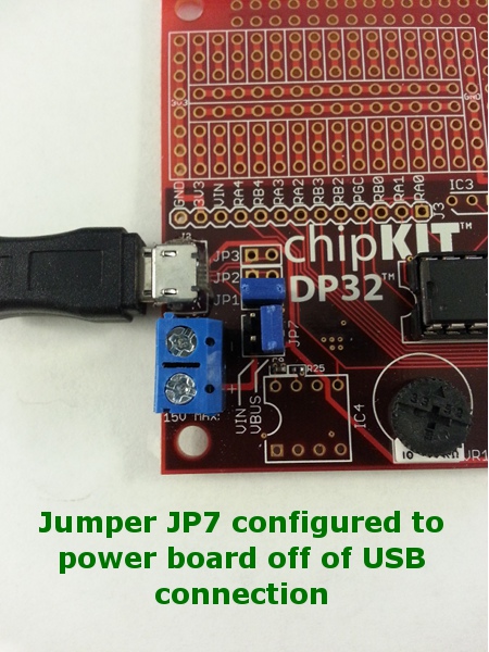
Hardware Setup:
The DP32 can be powered in a number of ways including from the USB connection (J2) or over the screw terminal (J6). The user needs to select which method will be used to power the board by configuring the jumpers immediately next to the screw terminal as shown below:
Procedure:
- Open MPIDE, by navigating to the extracted files in the folder you selected when you downloaded the source files. Locate the MPIDE executable (Windows® folder shown):
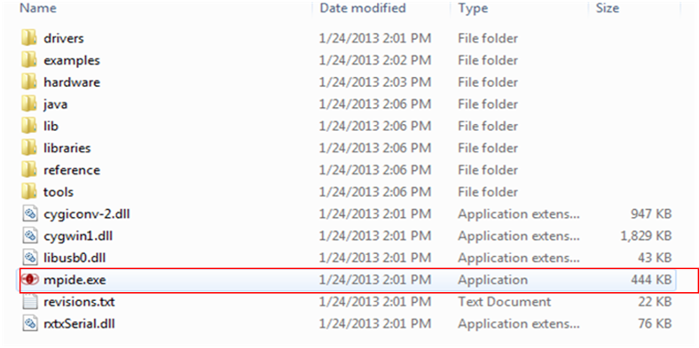
Double click the executable to open the MPIDE Hint: At this point it is a good idea to create a shortcut to the mpide.exe and place on your desktop.
- The first time you open MPIDE, you will be notified that a "sketchbook folder" will be created. In Windows, this folder will be located in the "My Documents" directory.
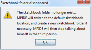
Click OK to continue.
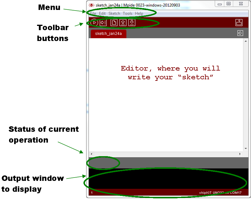
- The MPIDE Window should appear. Note the following main areas of the IDE Window.

- The chipKIT MPIDE comes with a variety of examples that can be used to help explore some of the various features of both the MPIDE and the chipKIT Platform. To access these examples, select File>Examples.
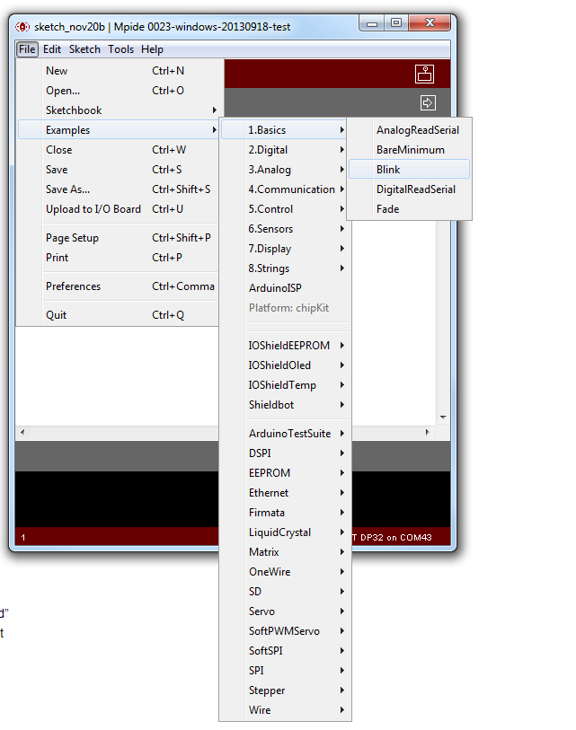
Note that there are all kinds of examples from lighting an LED on the chipKIT Board to different types of displays.Under File>Examples>Basic, there is an example called Blink. This example blinks an LED on the chipKIT Board ON/OFF in 1 second intervals. This little program is what is known as the "Hello World" program as it is usually the first application new users create who are using a Microcontroller for the first time.This example could easily be opened and run as is. However, in order to highlight some of the features of the MPIDE, this example will be recreated from scratch.
-
Click on the "New" button to open a new sketch window and then click "Save" button. Name the sketch something meaningful like DP32_Blink. The default directory will be the mpide folder created when the MPIDE was first started. Note: If you navigate to the mpide folder, there will now be a new folder with the name of the sketch you just saved.
-
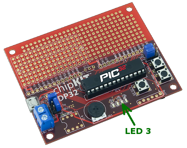
In this part of the tutorial, you will create a simple routine that will blink LED 3 on the
Add the following code into the MPIDE editor:
int ledPin = 43;                 // LED connected to digital pin 26
void setup()
{
  pinMode(ledPin, OUTPUT);      // sets the digital pin as output
}
void loop()
{
  digitalWrite(ledPin, HIGH);   // sets the LED on
  delay(1000);                  // waits for a second
  digitalWrite(ledPin, LOW);    // sets the LED off
  delay(1000);                  // waits for a second
}
-
There are quite a few things going on with this sketch. Under the "References" section at the top of the page, links are provided that will explain much of the content.Next, we will upload our code to the DP32.
-
Make sure that the chipKIT DP32 is connected via the mini-B connector on the board to an availableUSB port on the computer.
-
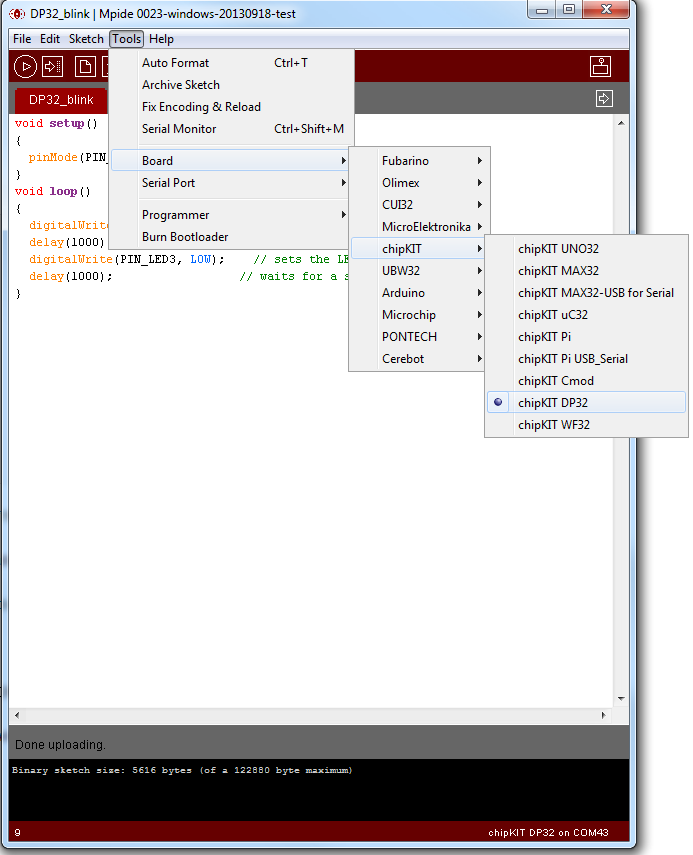
In MPIDE, select Tools>Board>chipKIT>chipKIT DP32 to identify the DP32 Board as a target select
Next, you will need to place the DP32 into "Programming" or "Bootloader" mode; otherwise, the sketch will not be able to be uploaded to the board. To enter into this mode, hold down the RESET button followed by the PGM button, then release the RESET button first, followed by the PGM button. You will know you've done this correctly if LED1 begins to flash repeatedly.
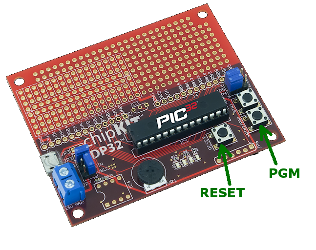
When the DP32 is in Bootloader mode, LED1 on the board will begin to flash on/off.
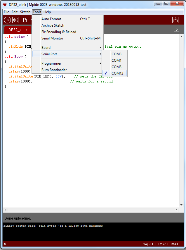
- Next, select Tools>Serial Port>COMxx. This will depend on which port was assigned to the chipKIT DP32 Board when first connected.
- To load your sketch onto the chipKIT DP32 board's Microcontroller, press the upload button. This will compile your sketch (check for errors) and then send to the Microcontroller.
Verifying Operation:
After the sketch is sent to the chipKIT DP32 board's Microcontroller, LED 3 on the chipKIT DP32 should flash on and off in 1 second intervals.