chipKIT® Development Platform
Inspired by Arduino™
- Get Started
- Learning
- Products
- Blog
- Beginner
For first time users of chipKIT modules. - Intermediate
For users who have a moderate exposure with chipKIT modules. - Advanced
For users who are experts with chipKIT modules. - Developers
- About Us
- Support
DIY chipKIT Board Using a Through-Hole SPDIP PIC32
Posted 2017-02-13 09:30:48 by MajenkoOverview
Certain varieties of Microchip Technology's PIC32 Microcontrollers are available in Small Plastic Dual In-line Packages (SPDIP). This packaging makes it very easy to build up your own chipKIT board at home using common tools found in the home hobbyist/Maker workshop. Other 32-bit platforms would require specialized equipment to solder their fine pitch packaging to a custom board.
This post will demonstrate how to build up a chipKIT Platform onto a solderless breadboard using a PIC32MX250F128B 32-bit Microcontroller and some readily available components.
[NOTE: This application uses a voltage provided off of the USB line. This is adequate for Low Power application such as blinking a single LED. However, most applications will require that you connect a separate power source to the Vin input of the Voltage Regulator such as a battery (shown at the end of this post). Excessive application power consumption could damage your USB port.]
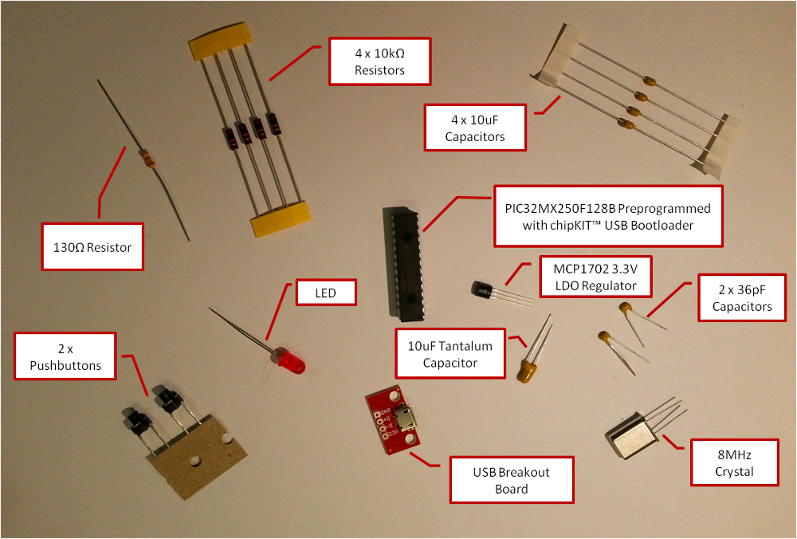
Components list
The following components were used to complete this project
- The TCHIP-USB-MX250F128B: Microchip PIC32MX250F128B in SPDIP package preprogrammed with the chipKIT USB Bootloader
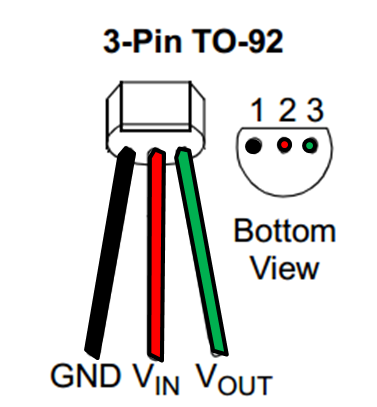
- Microchip MCP1702-3302E/TO: 3.3V LDO Voltage Regulator in TO-92 package
- 8MHz Crystal Oscillator
- 4 x 0.1uF Capacitors
- 1 x 10uF Tantalum or Ceramic capacitor (note: needed for low ESR characteristics)
- 2 x 36pF Capacitors
- 1 x 130Ω Resistor
- 4 x 10kΩ resistors
- LED
- 2 x SPST Tactile Switches
- Some sort of way to connect a USB cable to the breadboard. I used a Sparkfun BOB-09614 USB-mini Breakout board[ ]
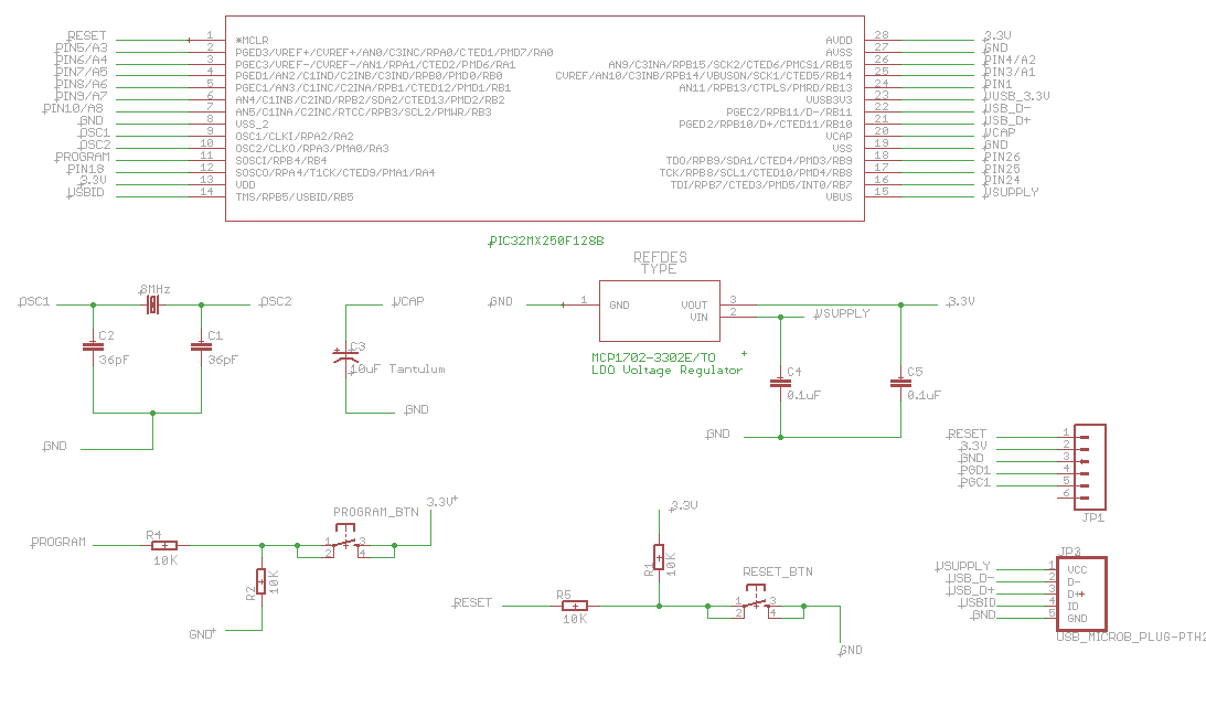
Schematic
Procedure
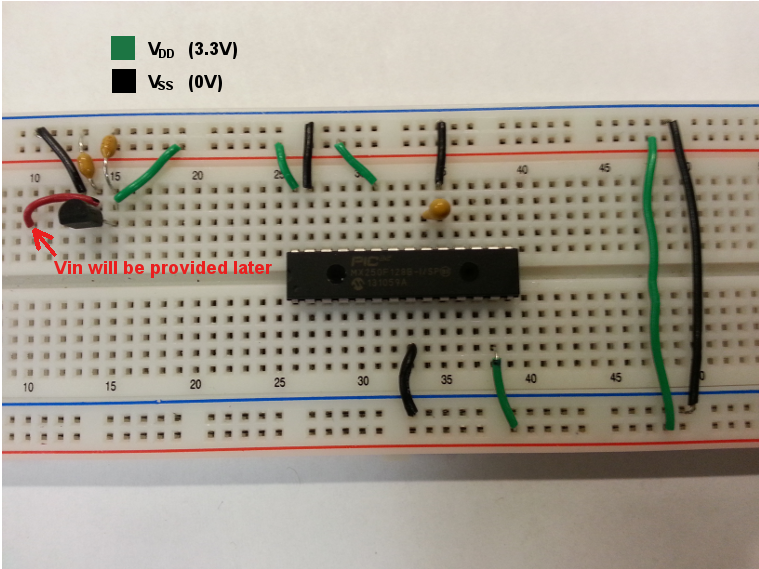
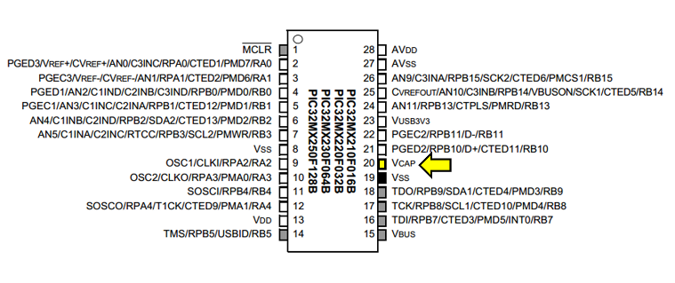
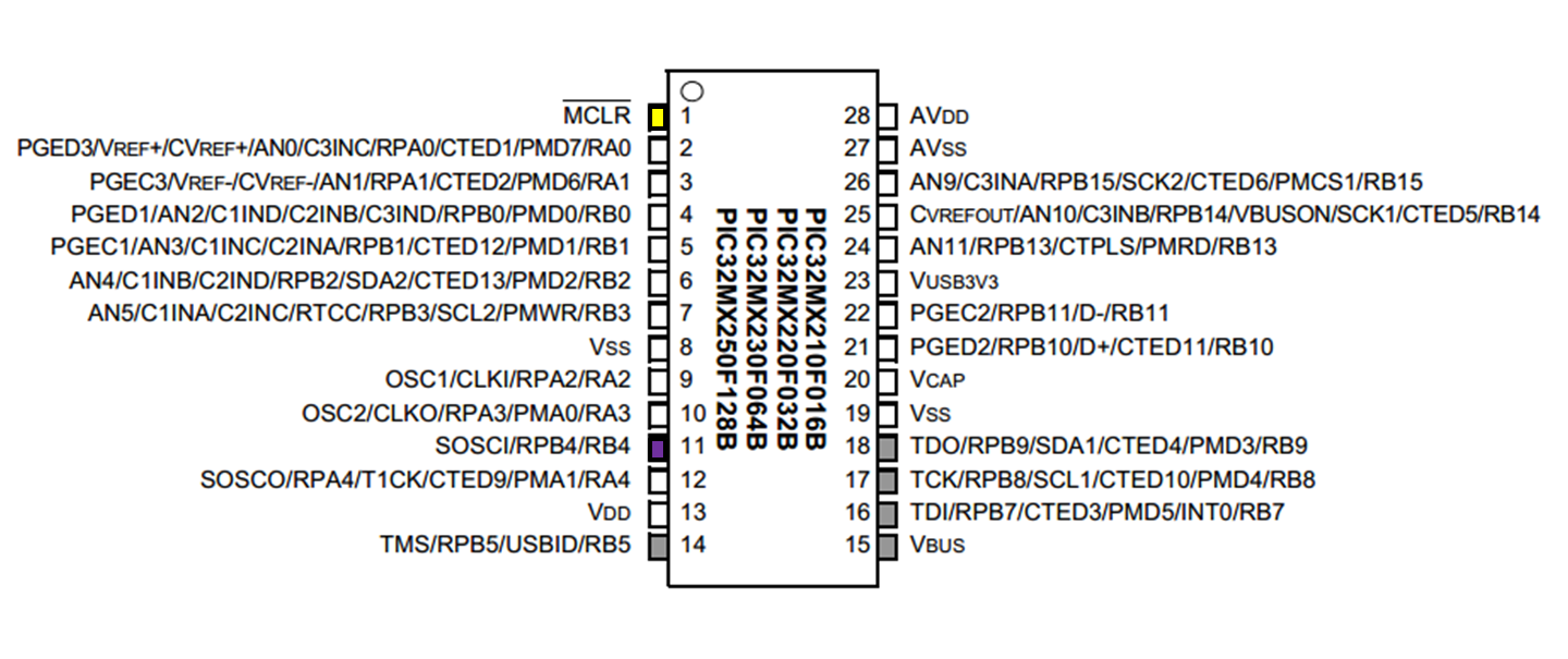
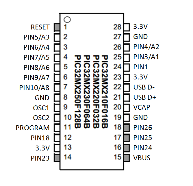
[Insert the PIC32MX250F128B into a solderless breadboard. Be sure to connect all of the Vdd (3.3V) and Vss (0V) signals as shown. Be sure to double check the datasheet pin diagram shown below:]
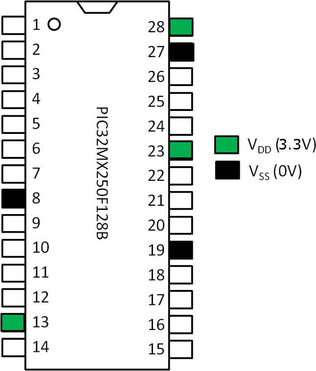
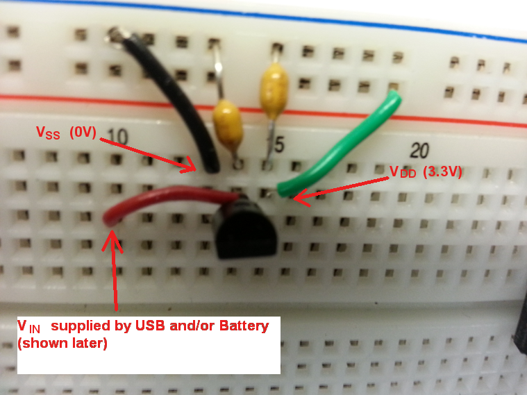
Note that some pins are not labeled as Vdd or Vss but will need to be connected to these voltages for the application to function. This includes pins related to USB and our Analog peripherals on the Microcontroller. Also note that the 3.3V Vdd signal will be coming off of our MCP1702 3.3V regulator. Connect the GND to a breadboard rail that will be dedicated to Vss and the Vout pin to a breadboard rail that will be dedicated to Vdd. Also connect a 0.1uF capacitor to the Vin and Vout pins to GND. The pin out diagram for the MCP1702 is shown below:
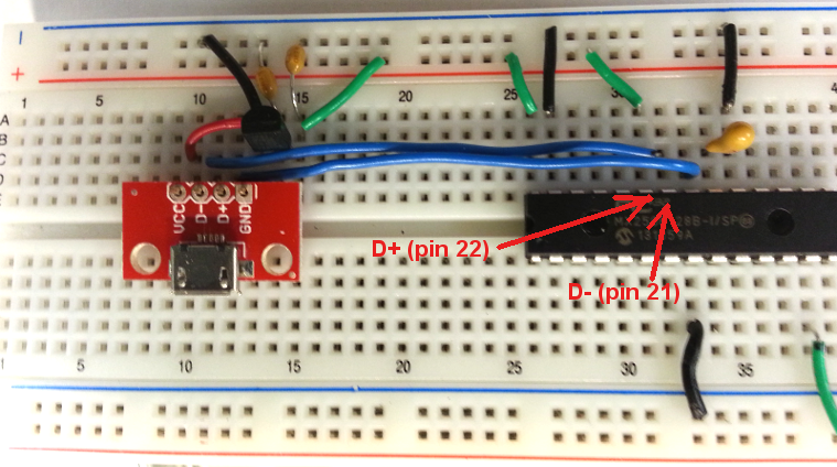
Next, the USB breakout board will be connected as follows:
- Provide the Vin signal for the MCP1702
- Connect the D- and D+ data lines
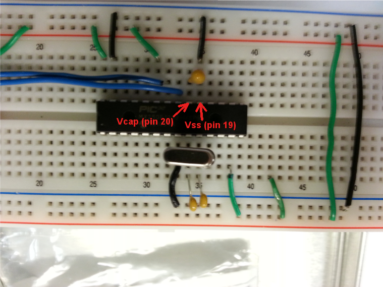
There is a Voltage Regulator on the PIC32MX250F128B Microcontroller that regulates internal voltage down to 1.8V to meet the requirement of the core. You don't really have to worry about this other than you will need to connect a low ESR capacitor such as a Tantalum type to the Vcap pin on the Microcontroller to ground (Vss) as shown:
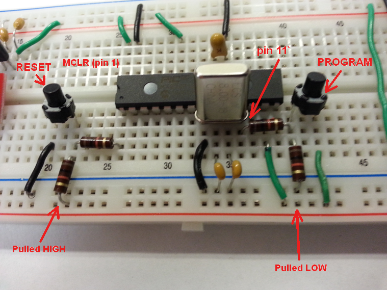
This particular version of the chipKIT Platform will use the PIC32MX250F128B's on-chip USB peripheral instead of the standard way of doing things with the FTDI chip. Therefore, we will need to tell the PIC32 when to go into "bootloader" mode. In order to download a sketch, the PIC32 will need to be in this "bootloader." To do this, two pushbuttons are used. One to RESET (turn on and off) the microcontroller and a second PROGRAM pushbutton that you will press down while the Microcontroller comes out of RESET. Coming out of RESET, the Microcontroller notices that the pin connected to the PROGRAM pushbutton has been driven HIGH (3.3V) and will automatically enter into "bootloader" mode.
The RESET pushbutton is connected to the MCLR (pin 1 of the Microcontroller) through a 10kΩ resistor that will limit current. The MCLR pin, when driven low, will cause the PIC32 to RESET. Therefore, another 10kΩ resistor is used to pull the line up to 3.3V that will keep the device out of RESET. One lead of the pushbutton is connected to this 3.3V signal and the other to Vss. Therefore, when the pushbutton is pressed, the Microcontroller will notice that the MCLR pin is driven LOW and will enter into RESET mode.
Similarly, the PROGRAM pushbutton is connected to the RB4 (pin 11) on the PIC32 through a current limiting 10kΩ resistor. However, this time the pin is held LOW through a 10kΩ pull down resistor since the a HIGH signal on this pin tells the Microcontroller to enter "bootloader" mode:
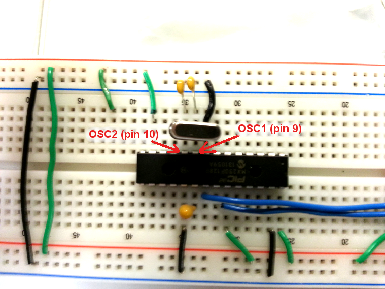
Finally, the USB bootloader is based off of an 8MHz external crystal oscillator. The oscillator is connected to the OSC1 and OSC2 pins on the PIC32 and 36pF capacitors are connected to each to ground as shown:
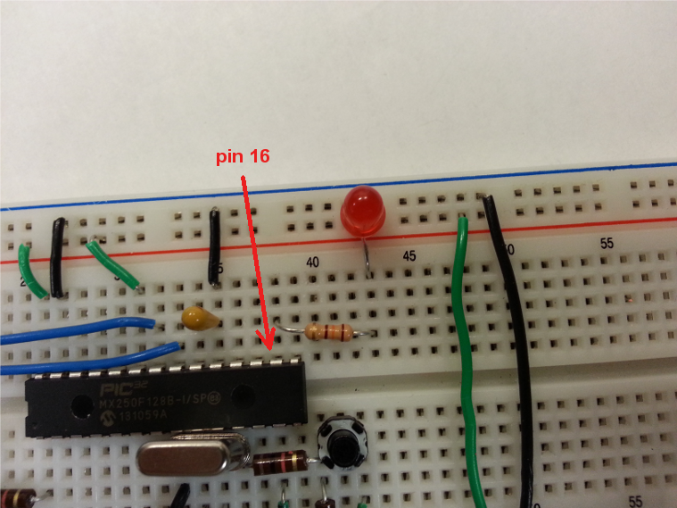
Next, I added a 130Ω resistor connected to pin 16 then to an LED connected to ground.
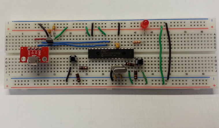
The final circuit should look something like this:
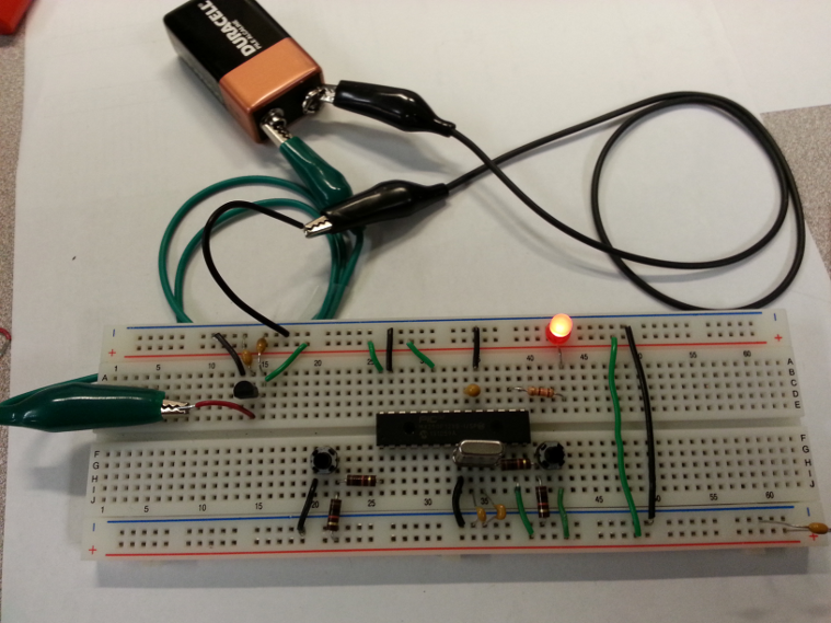
To connect to a battery source, disconnect the Vin input to the MCP1702 from the USB connector and connect to the positive terminal of a battery as shown. Make sure that the battery's negative terminal is connected to the Vss rail on your board.
Testing the Application
To test the application, we will create a sketch to blink the LED on pin 16, connect the board through the USB, and download the sketch.
Download MPIDE (a FREE download) from the Install page and install it, and then follow these instructions.
- Open up MPIDE and create a new sketch with the following code:
- Connect the application through the USB connector to your computer.
- If the driver is not installed successfully, you will need to manually install. The driver is located in the directory where you originally installed MPIDE. On my Window® Machine, I installed MPIDE to my C drive as follows:
- Once the device drivers are successfully installed, you are now ready to program the board.The PIC32MX250F128B chip is preprogrammed with the USB bootloader. The bootloader will only define which pin is used as the PROGRAM input (Pin 11 in this case) and which pins will flash to indicate that the device is indeed in bootloader mode. In this case, the LED indicator is defined as pin 7 on the PIC32MX250F128B Microcontroller. If you were to connect an LED to this pin as you did above for pin 16, the LED would flash rapidly when in "Bootloader" mode. In order to define which pin on the PIC32 will do what, we need to select a configuration in the MPIDE. We will be using an existing board definition file for the new Fubarino Mini platform.
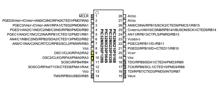
- In the MPIDE, select [Tools>Board>Fubarino Mini].The PIC32 will now be set up as follows:
- You will need to make sure that the application is in Bootloader mode. To do this, hold down the PROGRAM pushbutton connected to pin 11 while pressing on/off the pushbutton RESET connected to MCLR (pin 1).
- Select [Tools > Serial Port > COMx] (whatever serial comm has been assigned to the application)
- Click the upload button in MPIDE.
- The application USB will disconnect and then the LED connected to Digital Pin 24 should start flashing.
To view the pinout configuration and to locate some relevant tutorials, please visit the Fubarino Mini homepage at www.fubarino.org/mini.