chipKIT® Development Platform
Inspired by Arduino™
- Get Started
- Learning
- Products
- Blog
- Beginner
For first time users of chipKIT modules. - Intermediate
For users who have a moderate exposure with chipKIT modules. - Advanced
For users who are experts with chipKIT modules. - Developers
- About Us
- Support
DC Motor Control using Raspberry Pi, chipKIT Pi and the Arduino Motor Control Shield
Posted 2017-02-13 09:46:23 by MajenkoOverview
This post is intended to demonstrate compatibility of the chipKIT Pi with certain existing Arduino shields. In the second part of this post, we will also demonstrate how to communicate with the chipKIT Pi over a simple I/O line on the Raspberry Pi®, from a terminal window, to control the Arduino™ shield connected to the chipKIT Pi.
Hardware/Software Needed
- Raspberry Pi: http://www.raspberrypi.org/
- chipKIT Pi: http://www.element14.com/community/community/knode/dev_platforms_kits/element14_dev_kits/microchip-chipkit/chipkit_pi
- Arduino Motor Control Shield or other: http://arduino.cc/en/Main/ArduinoMotorShieldR3
Procedure
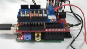
Let's begin by simply controlling a common Arduino shield. NOTE: Always check the electrical characteristics of any shield that will be connected to the chipKIT Pi. As with the Raspberry Pi, this is a 3.3V system. Therefore, if a shield outputs voltages greater than 3.3V there is a possibility that you could damage the chipKIT Pi or the Raspberry Pi. Connect the Arduino Motor Control Shield as shown:
- [Start a new sketch in MPIDE]
- [We will be using Brian Schmalz's SoftPWMServo library for this application. This is a very flexible library that will enable a PWM (square wave) output on any pin we like. This library comes already included as a core library with the MPIDE. Therefore, to use, simply add the header file to the library at the top of your sketch as follows:]
- The remainder of the sketch follows set up as per the Arduino Motor Control Shield specifications. I've added comments to explain each line of code.
//Include the SoftPWMServo Library
#include<SoftPWMServo.h>

void setup() {
    //set up channel B on the Arduino Motor Control Shield
    pinMode(13, OUTPUT); //Pin 13 controls direction
    pinMode(8, OUTPUT); //Pin 8 controls the brake
}

void loop() {
    //Turn the motor
    // First we disengage the brake for Channel B
    digitalWrite(8,LOW);

    //Depending on how your motor leads are connected to the Arduino
    //motor B header, the direction could be clockwise or counter clockwise
    //So let's just start by calling this direct 1 and drive pin 13 HIGH
    digitalWrite(13,HIGH);

    //We need to send a PWM to the Arduino MC shield to start the motor
    //turning. We also define a duty cycle that will set the motor speed.
    //The higher the duty cycle, the faster the motor will turn. Duty cycle
    //is set between 0 and 255.
    //So we send the PWM to pin 11 according to the Arduino MC specs at say
    // a duty cycle of 100
    SoftPWMServoPWMWrite(11, 100);

    //Let's run the motor for about 5 seconds
    delay(5000);

    //Now lets brake the motor
    digitalWrite(8,HIGH);

    //Give the motor a chance to settle
    delay(500);

    //change directions
    digitalWrite(13,LOW);

    //and run the motor for about 5seconds in the other direction
    delay(5000);

    //Again, we brake the motor
    digitalWrite(8,HIGH);

    //give the motor a chance to settle
    delay(500);

//and repeat
}
So, this is nothing really special and can be done on any chipKIT Board. However, we can make something pretty interesting by introducing some Python-based communication from the Raspberry Pi to the PIC32 MCU on the chipKIT Pi. Proceed to the next page to continue. In this example, a General Purpose Input/output line on the Raspberry Pi Expansion Connector will be used to send a HIGH or LOW logic level from the Pi to the chipKIT Pi to turn the motor on or off.
Hardware Setup
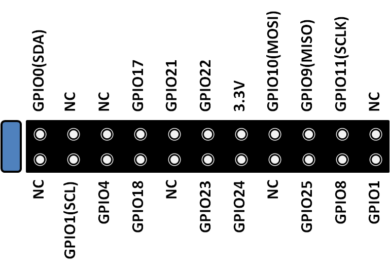
Simply connect a jumper wire from the J1 RPi-Connect header in the upper left corner of the chipKIT Pi. Here I've connected the third pin down on the bottom side of the header which is GPIO4 as per the diagram below.
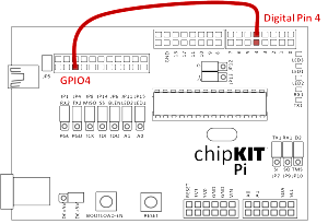
We will connect this pin to an available input on the chipKIT Pi. Referring to the Arduino Motor Control Shield Schematic, we note that pin 4 is available. This conveniently has the same number as our GPIO on the Raspberry.
This connection is illustrated below. (Note that the Arduino Motor Control Shield is not shown to make it easier to see this connection.)
Software Setup
In this application example, when the GPIO4 line is driven HIGH (3.3V) by the Raspberry Pi, the chipKIT Pi will read this and turn on the motor. When the GPIO4 line is driven LOW (0V) the chipKIT Pi will turn off the motor. Let's setup the chipKIT Pi sketch first. The sketch is setup as it was in the previous example only adding Digital Pin 4 as an input that will receive the signal from the Raspberry Pi. In the loop(), the code first checks digital pin 4, if it reads a LOW/False/0V signal it calls the function allStop() which simply applies the brake signal on pin 8. If it reads a HIGH/True/5V signal it will call the turn() function that disengages the brake for 5 seconds, then reapplies the brake. The full sketch is below:
//Include the SoftPWMServo Library
#include <SoftPWMServo.h>

int Pi_GPIO = 0;

void setup() {
    //set up channel B on the Arduino Motor Control Shield
    pinMode(13, OUTPUT); //Pin 13 controls direction
    pinMode(8, OUTPUT); //Pin 8 controls the brake
    pinMode(4, INPUT); //Input line from Raspberry PI GPIO
}

void loop() {
    //We need to send a PWM to the Arduino MC shield to start the motor
    //turning. We also define a duty cycle that will set the motor speed.
    //The higher the duty cycle, the faster the motor will turn. Duty cycle
    //is set between 0 and 255.
    //So we send the PWM to pin 11 according to the Arduino MC specs at say
    // a duty cycle of 100
    SoftPWMServoPWMWrite(11, 100);

    //Read the inputs from the Raspberry Pi
    Pi_GPIO = digitalRead(4);

    //Generate motor output based on inputs from the Pi
    if (Pi_GPIO == 0) {
        allStop();
    } else if (Pi_GPIO == 1) {
        turn();
    }
}

void turn() {
    //Set for directionA
    digitalWrite(13,HIGH);

    // First we disengage the brake for Channel B
    digitalWrite(8,LOW);

    //Let's run the motor for about 5 seconds
    delay(5000);

    //brake the motor
    digitalWrite(8,HIGH);

//give the motor a chance to settle
    delay(500);
}

void allStop() {
    //brake the motor
    digitalWrite(8,HIGH);

    //give the motor a chance to settle
    delay(500);
}
Place the chipKIT Pi into bootloader mode and download the sketch.
In order to communicate with chipKIT Pi, we will need to download the GPIO package for Python as follows:
Installing GPIO Package for Python
Open a terminal window and download the latest version of the GPIO Package for Raspberry Pi. At the time of this post, the latest version was RPi.GPIO-0.5.3a:
$ sudo apt-get update
$ sudo apt-get -y install python-rpi.gpio
Next step, open python within the terminal window (note Python 3 is used here):
$ sudo python
Instead of typing the full RPi.GPIO name every time, we will set it up so that using just GPIO does the same thing:
>>> import RPi.GPIO as GPIO
Next, we need to define the type of numbering we will use
GPIO.setmode(GPIO.BCM) — Broadcom GPIO numbering
or
GPIO.setmode(GPIO.BOARD) — board pin numbering
Here I used BCM. If you need more of an explanation on this, there are tons of resources on the web to explain this.
>>> GPIO.setmode(GPIO.BCM)
Now we need to let the Raspberry Pi know that we will be using GPIO4 as an output:
>>> GPIO.setup(4, GPIO.OUT)
Finally, to send a HIGH/True/3.3V over the selected pin:
>>> GPIO.output(4, True)
Note that if all went as planned the motor connected should now start turning. To send a LOW/False/0V over the selected pin to turn off the motor:
>>> GPIO.output(11, False)
The complete terminal code is show below:
pi@raspberrypi ~ $ sudo python3
Python 3.2.3 (default, Mar 1 2013, 11:53:50)
[GCC 4.6.3] on linux2
Type "help", "copyright", "credits" or "license" for more information.
>>> import RPi.GPIO as GPIO
>>> GPIO.setmode(GPIO.BCM)
>>> GPIO.setup(4, GPIO.OUT)
>>> GPIO.output(4, False)
>>> GPIO.output(4, True)
>>> GPIO.output(4, False)