chipKIT® Development Platform
Inspired by Arduino™
- Get Started
- Learning
- Products
- Blog
- Beginner
For first time users of chipKIT modules. - Intermediate
For users who have a moderate exposure with chipKIT modules. - Advanced
For users who are experts with chipKIT modules. - Developers
- About Us
- Support
Misc HW info
Created Mon, 30 May 2011 06:13:43 +0000 by hobbified
hobbified
Mon, 30 May 2011 06:13:43 +0000
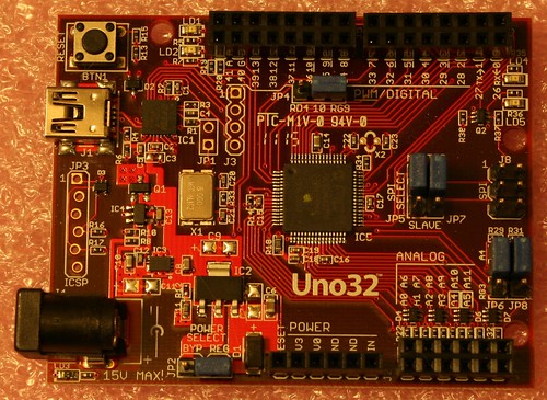
This is just some stuff (of interest to me) that I've gleaned from the photos, please feel free to correct or add to it.
Voltage regulation: similar to the Arduino boards, the chipkit boards use an LDO linear regulator to drop external (non-USB) DC input down to 5V, and a second LDO linear regulator to provide 3.3V from the 5V (whether running on USB or not). The first regulator is an NCP1117, rated for 1A and with a dropout of slightly more than 1V. This is slightly beefier than the MC33269 on the current Arduino boards, but basically it's very similar and has similar limitations (if you feed it less than about 6.5V the voltage will probably dip under load, and if you feed it more than 9V or so it's going to get quite hot and inefficient, since linear regulators turn as much power into heat as necessary to keep their output at the nominal level). The 3.3V regulator is an MCP1725 rated for 500mA and only 0.2-0.3V dropout. This is fatter than the 50 - 150mA available on the 3.3V line of an Arduino (depending on whether or not it has an FTDI chip), which makes sense since the PIC32 runs on 3.3V.
Timekeeping: the crystal is an 8MHz one (Fox FQ7050B-8.000), apparently premultiplied by 10x in the PIC32 to get the 80MHz system clock. The 32kHz crystal doesn't seem to be populated. The 8MHz crystal is supposed to have a +/- 30ppm tolerance at design temp of 25C, +/- another 30ppm over its design temp range of 0-70C. This isn't exactly stellar, but given that the crystal on my Arduino is about 250ppm out at 25C, and is temperature-sensitive to the tune of 10-15 ppm per degree, the chipkit sounds more promising once again.
WestfW
Tue, 31 May 2011 05:10:02 +0000
Well, I've done this for Arduino and Arduino Mega, so I might as well continue. Here (linked to) is an "annotated" picture of one of the Uno32 boards, with notes describing most of the significant features (and some of the insignificant features as well.)
JLC333
Tue, 31 May 2011 09:33:35 +0000
Hello,
thanks for those informations.
Do you know where electrical data can be found please ? I'm looking for consumption, voltages, and so on.
Regards.
GeneApperson
Wed, 01 Jun 2011 22:34:10 +0000
The NCP1117 is the preferred part, but an LM1117 will also work for the 5V regulator. Depending on part availability, a future build may use the LM1117 instead. The board is actually layed out to use either fixed 5V or adjustable versions of either part. There have been some crazy availablity/lead time issues for ICs the last year or so, and I didn't want to get burned by availability of a single source part.
I also put in a jumper to bypass the 5V regulator. This is to allow the board to be operated from an externally regulated 5V supply, or if the 5V rail isn't critical, it can be operated from a supply down to about 3.6V. If this jumper is in the bypass position, it is important to observe the 6V max input voltage of the MCP1725.
Gene Apperson Digilent