chipKIT® Development Platform
Inspired by Arduino™
- Get Started
- Learning
- Products
- Blog
- Beginner
For first time users of chipKIT modules. - Intermediate
For users who have a moderate exposure with chipKIT modules. - Advanced
For users who are experts with chipKIT modules. - Developers
- About Us
- Support
Servo Control Issue using chipKIT MAX32 Board
Created Tue, 16 Aug 2016 17:39:51 +0000 by Denco
Denco
Tue, 16 Aug 2016 17:39:51 +0000
Hello,
I am working on a project using a 5V DC servo (towerpro SG5010, [https://www.adafruit.com/product/155] ), controlled by a chipKIT Max 32. The problem I am having is that I cannot control the servo using the MAX 32. The simple servo sweep test wont even work.
To troubleshoot this I have tried a number of different things:
- The circuit is set up fine as a smaller servo motor will work as expected.
- I tried powering the micro-controller via power socket and then I created a dedicated 5V supply to the servo, both in case there wasn't enough juice.
The curious thing is that the setup/servo works perfect when I use an Arduino Uno to run the sketch. The Uno can directly run the servo, so power isn't an issue.
I made a simple sketch that moves the servo to a set angle when a button is pressed and returns when released. This also works fine on the Arduino. The only difference I can see with the two setups is that the pin used for the pwm signal on the Arduino has a starting voltage of 0.54V before the button is pressed, reducing to 0.135V when the button is held and the servo is at final angle. In contrast, the values on the MAX32 are 0.388V and 0.09V
Could this lower voltage be the cause of the issue or why can I not control this servo on the chipKIT?
If it is the cause, is there any way to increase this output voltage?
I am new to using servos and micro-controllers so any help would be appreciated. Thanks.
majenko
Tue, 16 Aug 2016 18:22:49 +0000
Measuring the voltage of a PWM pin is not the most useful diagnostic - you really need an oscilloscope to see the waveform. Still, it is possible to pull some useful information out of it...
The Arduino is a 5V device, whereas the chipKIT is a 3.3V device. This means that on the Arduino the PWM is a square-wave waveform at 5V, whereas on the chipKIT it is a square-wave waveform at 3.3V. The duty cycle defines the percentage of the voltage that you see on your volt meter.
So we can do some calculations. 3.3V is 5V * 0.66, so let's use that factor for the other voltages:
0.54 * 0.66 = 0.36 0.135 * 0.66 = 0.089
So you can see that the numbers, given the difference in logic level voltage, are pretty much spot on. You're getting the same duty cycle.
So the question remains - can the servo work with 3.3V logic levels? The answer is: I don't know. There is a singular lack of technical information about the interface on the tower pro motors. Most likely it all depends on what voltage you are powering the motor at - most things these days have the logic HIGH level (V_IH) as a percentage (60%) of the supply voltage. At 5V supply that is 3V, so should work fine. At 6V though that will be 3.6V, which is way above the chipKIT's output.
If that is the case then try running the motor from a slightly lower voltage (4.5V, 3xAA). If you can't do that then you will have to use a 3.3V -> 5V logic level converter.
Denco
Wed, 17 Aug 2016 12:58:32 +0000
Thank you for your detailed reply majenko, it was very informative. I will try both suggestions. Just in relation to the logic level converter, will that scale the output i.e. if it gets 0.36V in will it output 0.54V or does it only output 5V when it gets a 3.3V signal? That is probably a stupid question but I have a mechanical background. Thanks.
majenko
Wed, 17 Aug 2016 15:32:49 +0000
The level converter outputs 5V when it gets 3.3V.
To put it in a mechanical context - PWM is like the teeth of a cog. It has both high points and low points. The diameter of the cog can be the diameter between opposite high points, or opposite low points. Or you could have the average diameter. It's that "average diameter" that you are measuring with your volt meter.
The level shifter just makes the teeth longer so they mesh with another cog that would be slightly too far away otherwise.
Denco
Wed, 17 Aug 2016 23:19:49 +0000
Thanks again majenko.
I found a image of two level shifting circuits posted on another forum where the question of converting a 3.3V pwm signal to a 5V pwm signal was raised. I will try out one of them tomorrow if I can get my hands on the suggested transistor. Hopefully this will sort the issue. (ref. http://www.redrok.com/images/3.3V_to_5V_Level-shifter.png)
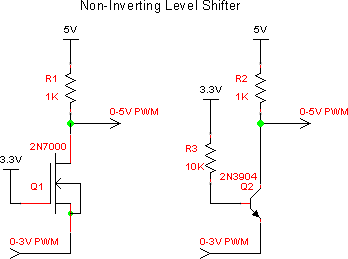
majenko
Thu, 18 Aug 2016 00:20:29 +0000
Any small signal NPN transistor will do, or any logic-level N-channel MOSFET (one with a threshold less than 2V).