chipKIT® Development Platform
Inspired by Arduino™
- Get Started
- Learning
- Products
- Blog
- Beginner
For first time users of chipKIT modules. - Intermediate
For users who have a moderate exposure with chipKIT modules. - Advanced
For users who are experts with chipKIT modules. - Developers
- About Us
- Support
FFT from Analog signal frequency
Created Tue, 26 Aug 2014 09:04:01 +0000 by citizen3942
citizen3942
Tue, 26 Aug 2014 09:04:01 +0000
Hi, I am developing a frequency counter/analyzer. I need to read Analog signal from 0 up to 200000 Hz, transform it with FFT and find the highest amplitude peak thus giving me the correct frequency. I would prefer to have the FFT resolution to be as high as possible, lets say 400000 amplitude values and from that find the highest peak.
When the actual frequency is found I need to display this number on 7-segment LED display in multiplex method.
I have created a code to have the segment display working and show numbers, but the most difficult part seems to be the "Analog->FFT->Frequency value" part.
Here is my robust code so far:
/*
 * Frequency Sensor Displayed on 6 Digit 7 segment common anode
 * 2013
 */

#include "math.h"

const int digitPins[6] = {
  2,3,4,5,6,7};                 //6 common anode pins of the display
//Pin connected to ST_CP(12) of 74HC595
int latchPin = 8;
//Pin connected to SH_CP(11) of 74HC595
int clockPin = 12;
//Pin connected to DS(14) of 74HC595
int dataPin = 11;
const int freqPin = 12;     //frequency input pin
const byte digit[11] =      //seven segment digits in bits
{
  192, //0
  249, //1
  164, //2
  176, //3
  153, //4
  146, //5
  130, //6
  248, //7
  128, //8
  144, //9
  255  //max dimmed
};
// Setup the combination to display each number on the display
byte ZERO = 192; // A number value goes here.
byte ONE = 249;
byte TWO = 164;
byte THREE = 176;
byte FOUR = 153;
byte FIVE = 146;
byte SIX = 130;
byte SEVEN = 248;
byte EIGHT = 128;
byte NINE = 144;
byte MAX = 127;
byte numberBuffer[6] = {0};
int digitBuffer[6]={0};
int digitScan = 0, flag=0,  soft_scaler = 0, count=0;
int refreshRate = 2500; //refresh rate in microseconds best 2800
int freq=1234,freqTmp=0;
boolean dim=true;

void setup(){
  for(int i=0;i<6;i++)
  {
    pinMode(digitPins[i],OUTPUT);
  }
  pinMode(freqPin, INPUT);
  pinMode(latchPin, OUTPUT);
  pinMode(clockPin, OUTPUT);
  pinMode(dataPin, OUTPUT);
//  Serial.begin(9600);
}

void loop(){

  if(freq>999999)freq=0;

  updateBuffer();
  updateDisp();

  count++;
  if(count>int(1000000/(7*refreshRate))){freq++;count=0;} //7=number of digits+loop delay

  delayMicroseconds(refreshRate);
}

//writes the number on display
void updateDisp(){
  for(int i=0; i<6; i++){
      for(int j=0; j<6; j++){
        digitalWrite(digitPins[j], LOW);
      }

    digitalWrite(latchPin, LOW);

    shiftOut(dataPin, clockPin, MSBFIRST, numberBuffer[i]);

    digitalWrite(latchPin, HIGH);

    digitalWrite(digitPins[i], HIGH);

    delayMicroseconds(refreshRate);
  }
}

//updates number buffer
void updateBuffer(){
  dim=true;
  freqTmp=freq;
  for(int i=0;i<6;i++){
    digitBuffer[5-i] = freqTmp % 10;
    freqTmp /= 10;
    if(digitBuffer[i]==0&&dim==true){
       numberBuffer[i]=digit[10];
    }else{
      dim=false;
      if(i==2){
        numberBuffer[i]=digit[digitBuffer[i]]-128; //print the decimal point on the 3rd digit
      }else{
        numberBuffer[i]=digit[digitBuffer[i]];
      }
    }
  }
}
Now the question is: How to read the signal, transform it and show the number value? It has to be made fast in order to update the display in 500ms or 1000ms time so that there is no noticable flickering.
PS! At instructables there is a similar project for reading the frequency of analog signal, but it is made for Arduino and it doesn't have the Segment display nor FFT. Maybe it is a better option but i believe that having an FFT gives me higher accuracy. Here is the link at Instructables.
majenko
Tue, 26 Aug 2014 10:20:11 +0000
Ok, so there's quite a lot here you'll need to understand and maybe change your thinking on.
Firstly I see you're using shift registers and shiftOut() for driving your displays. That is a rather slow method and prone to causing blockages. Much better would be to directly wire the displays to the chipKIT and drive them as IO ports. Ideally would be using pins 26-33 (assuming UNO32/ MAX32 or similar) as that is the lower 8 bits of port E, so you can directly drive all 8 pins as a single operation.
Secondly, detaching the displays and its code from the "foreground" and driving it with a timer and interrupt would basically mean that the display would always function smoothly regardless of whatever else you were doing.
Timer library here: [url]https://github.com/majenkotech/Timer[/url]
Ok, so that's the display sorted. Now for the "sampling".
Your signal - is it a true analog waveform, or are you just wanting to count / measure pulses on a digital square wave? If the latter, which is what most frequency counter projects are, then FFT makes no sense as the only frequency that is of interest is the lowest frequency - i.e., the time between pusles. However, if it is a proper analog waveform, such as sound from a microphone, or similar, then sampling it is a considerably more difficult operation.
For digital pulse measuring / counting simply connect your signal to one of the interrupt pins, and attach an interrupt with attachInterrupt() then count the pulses that come in over a pre-defined time frame. Divide the pulses by the time, and you get the frequency.
For a real analog signal you will need to understand a couple of things extra:
- To FFT you need a sample set. The larger the sample set the higher your FFT bucket resolution. The number of FFT buckets (one bucket is a range of frequencies) is half the number of samples you have in your sample set.
- The larger your sample set the more memory it needs, and the longer it takes to read in that sample set.
- According to the Nyquist-Shannon theorem you need to sample at double the highest frequency you want to work with, so for a 200KHz frequency you will have to sample at 400KHz.
- The higher the frequency you sample at the larger each FFT bucket is.
So say you sample at 400Kz (the PIC32 ADC is capable of up to 1.1Msps, but getting it right is a black art) for a 200KHz signal, and you have a sample set of 8192 samples (the sample set should be a 2[sub]n[/sub] value) at 12-bit resolution, (that results in memory usage of 16384 bytes of course), the sampling would take 20.48ms to fill the set. You then double the memory usage of course, to create the (0 value initially) complex component of the signal, so you're now up to 32768 bytes of sample memory.
You would end up with 4096 FFT buckets after transforming the set, each one covering 200,000/4096 = 48.828Hz.
Of course, you then also need to take the resultant complex amplitude / phase vectors and convert them into an absolute amplitude (Pythagoras?) before comparing them and finding the maximum.
Getting the PIC32 to sample at, sat, 400000sps is not easy. analogRead() will not cut it, not by a long way. You need to manually configure the ADC and a timer to drive it to run at 400KHz, and use DMA to read the data smoothly from the ADC and place it directly in memory as the samples become available. As I mentioned - it's a black art. Not all the chipKIT boards have DMA (the Uno32 doesn't) - check the chip on yours and refer to the data sheet for it.
Scared yet?
citizen3942
Wed, 27 Aug 2014 10:55:54 +0000
The FFT part seems to be quite scary to me but I think I will bypass that part of my design and use Schmitt trigger instead to digitize my analog signal and the try to read pulses.
There is only one downside in Schmitt triggering. The analog signal threshold might not be the same all the time and this might give me a wrong reading. I don't know yet how to automatically adjust the trigger to 50% signal amplitude.
By far I have reconstructed my segment display code with suggested Timer interrupt. So here it is:
#include <Timer.h>
#include "math.h"

// Create a new timer object using T4
Timer4 timer;

const int PRESCALE = 600;

const int digitPins[6] = {
  2,3,4,5,6,7};                 //6 common anode pins of the display
const int segmentPins[8] = {
  34,35,36,37,38,39,40,41};      //8 segment pins of the display

int digitBuffer[6]={0};

boolean digits[10][7] = {
{1,1,1,1,1,1,0},//0
{0,1,1,0,0,0,0},//1
{1,1,0,1,1,0,1},//2
{1,1,1,1,0,0,1},//3
{0,1,1,0,0,1,1},//4
{1,0,1,1,0,1,1},//5
{1,0,1,1,1,1,1},//6
{1,1,1,0,0,0,0},//7
{1,1,1,1,1,1,1},//8
{1,1,1,1,0,1,1},//9
};

int freq=0,freqTmp=0;
int digitCnt=0;
//int refreshRate = 2000; //refresh rate in microseconds best 2800

//updates digit buffer
void updateBuffer(){
  boolean dim=true;
  freqTmp=freq;
  for(int i=0;i<6;i++){ //add digits to buffer
    digitBuffer[5-i] = freqTmp % 10;
    freqTmp /= 10;
  }
  for(int i=0;i<6;i++){ //dim pre-zeroes
	if(digitBuffer[i]==0&&dim==true){
		digitBuffer[i]=10;
	}else{
		dim=false;
	}
  }
}

//update segment digital pins
void updateSegments(int digit, boolean dot=0){
	for(int i=0;i<8;i++){
		digitalWrite(segmentPins[i], HIGH);
	}

	for(int i=0;i<7;i++){
		if(digit==10){
			//do nothing - leave all digital pins high
		}else{
			if(digits[digit][i]){
				digitalWrite(segmentPins[i], LOW);
			}
		}
	}

	if(dot){ //add dot if set true
		digitalWrite(segmentPins[7], LOW);
	}

}

//writes the number on display
void updateDisp(){
  updateBuffer();

    for(int j=0; j<6; j++){
        digitalWrite(digitPins[j], LOW);
    }

    if (digitCnt==2){ //add a dot to the 3rd digit
            if(digitBuffer[digitCnt]==10){ //if there is empty digit, then do not add dot
                updateSegments(digitBuffer[digitCnt]);
            }else{
                updateSegments(digitBuffer[digitCnt],1);
            }
	}else{
		updateSegments(digitBuffer[digitCnt]);
	}

	digitalWrite(digitPins[digitCnt], HIGH);

	digitCnt++;
	if(digitCnt == 6){
		digitCnt = 0;
	}
}

// Be sure to set the ISR routine to be an interrupt
void __attribute__((interrupt)) isr() {

	updateDisp();

	// And tell the chip we have handled the interrupt by
	// clearing the flag.
	clearIntFlag(_TIMER_4_IRQ);
}

void setup() {
	for(int i=0;i<6;i++)
	{
		pinMode(digitPins[i],OUTPUT);
	}
	for(int i=0;i<8;i++)
	{
		pinMode(segmentPins[i],OUTPUT);
	}

	timer.setFrequency(PRESCALE);

	// Link in out ISR routine. Note, it is a real ISR routine,
	// so requires all the right attributes etc.
	timer.attachInterrupt(isr);

	// Start the timer running,
	timer.start();
}

void loop() {
		freq++;
		if(freq>999999)freq=0;
		delay(50);
}
Now - how to create a pulse reading code and how to automatically trigger the analog signal at 50% amplitude to form the pulsing signal which I can read and transform into frequency? The analog signal is sinusoidal and may have few bumps within and filtering these out might be another issue. Maybe it is possible to do it in code as well
majenko
Wed, 27 Aug 2014 11:15:05 +0000
If the signal is a near clean sine wave, and you're only interested in its lowest (and usually strongest) frequency component, you could amplify the signal to a level that is much higher than the input levels then clip it down to fit the right input range.

The more you amplify and clip the closer to a square wave you end up with.
citizen3942
Wed, 27 Aug 2014 12:12:08 +0000
Well this method I guess can be used when the analog signal oscillates around 0V. In my application the analog signal is between 0-5V. In some applications the signal amplitude is quite small - lets say 100-200mV. But when I overamplify the signal then the faint noise in the signal is also amplified. I don't know if clipping is such a good idea here.
citizen3942
Thu, 28 Aug 2014 07:19:54 +0000
I have tried to implement the instructables version in reading the analog signal frequency, but I am getting nowhere.
........
Timer5 timer2;

//data storage variables
byte newData = 0;
byte prevData = 0;
unsigned int time = 0;//keeps time and sends vales to store in timer[] occasionally
int timer3[10];//sstorage for timing of events
int slope[10];//storage for slope of events
unsigned int totalTimer;//used to calculate period
unsigned int period;//storage for period of wave
byte storIndex = 0;//current storage index
int maxSlope = 0;//used to calculate max slope as trigger point
int newSlope;//storage for incoming slope data

//variables for decided whether you have a match
byte noMatch = 0;//counts how many non-matches you've received to reset variables if it's been too long
byte slopeTol = 3;//slope tolerance- adjust this if you need
int timerTol = 10;//timer tolerance- adjust this if you need

//variables for amp detection
unsigned int ampTimer = 0;
byte maxAmp = 0;
byte checkMaxAmp;
byte ampThreshold = 30;//raise if you have a very noisy signal
.....
const int SIGNALTICK = 56000;
const int THRESHOLD = 770;
......
const int sensorPin = A0;
void reset(){//clear out some variables
  storIndex = 0;//reset index
  noMatch = 0;//reset match couner
  maxSlope = 0;//reset slope
}
.......
void __attribute__((interrupt)) isr2() {
  digitalWrite(28, LOW);//set pin 28 low
  prevData = newData;//store previous value
  newData = analogRead(sensorPin);//get value from A0
  if (prevData < THRESHOLD && newData >=THRESHOLD){//if increasing and crossing midpoint
    newSlope = newData - prevData;//calculate slope
    if (abs(newSlope-maxSlope)<slopeTol){//if slopes are ==
      //record new data and reset time
      slope[storIndex] = newSlope;
      timer3[storIndex] = time;
      time = 0;
      if (storIndex == 0){//new max slope just reset
        digitalWrite(28, HIGH);//set pin 28 high
        noMatch = 0;
        storIndex++;//increment index
      }
      else if (abs(timer3[0]-timer3[storIndex])<timerTol && abs(slope[0]-newSlope)<slopeTol){//if timer duration and slopes match
        //sum timer values
        totalTimer = 0;
        for (byte i=0;i<storIndex;i++){
          totalTimer+=timer3[i];
        }
        period = totalTimer;//set period
        //reset new zero index values to compare with
        timer3[0] = timer3[storIndex];
        slope[0] = slope[storIndex];
        storIndex = 1;//set index to 1
        digitalWrite(28, HIGH);//set pin 28 high
        noMatch = 0;
      }
      else{//crossing midpoint but not match
        storIndex++;//increment index
        if (storIndex > 9){
          reset();
        }
      }
    }
    else if (newSlope>maxSlope){//if new slope is much larger than max slope
      maxSlope = newSlope;
      time = 0;//reset clock
      noMatch = 0;
      storIndex = 0;//reset index
    }
    else{//slope not steep enough
      noMatch++;//increment no match counter
      if (noMatch>9){
        reset();
      }
    }
  }

  time++;//increment timer at rate of 38.5kHz

  ampTimer++;//increment amplitude timer
  if (abs(THRESHOLD-analogRead(sensorPin))>maxAmp){
    maxAmp = abs(THRESHOLD-analogRead(sensorPin));
  }
  if (ampTimer==1000){
    ampTimer = 0;
    checkMaxAmp = maxAmp;
    maxAmp = 0;
  }
  // And tell the chip we have handled the interrupt by
  // clearing the flag.
  clearIntFlag(_TIMER_5_IRQ);
}
.....
void setup() {
.....
   pinMode(28,OUTPUT);//output pin
        pinMode(sensorPin, INPUT); //declare sensor pin as input

	// The timer can't do a 1Hz interrupt, so let's do 10Hz and
	// manually pre-scale it down.
	timer.setFrequency(PRESCALE);
        timer2.setFrequency(SIGNALTICK);

	// Link in out ISR routine. Note, it is a real ISR routine,
	// so requires all the right attributes etc.
	timer.attachInterrupt(isr);
        timer2.attachInterrupt(isr2);

	// Start the timer running,
	timer.start();
        timer2.start();
}
void loop() {
  if (checkMaxAmp>ampThreshold){
    freq=SIGNALTICK/period;
  }
  delay(500);
}
Any Ideas???
majenko
Thu, 28 Aug 2014 07:55:41 +0000
Any global variables used in an ISR must be flagged as "volatile":
volatile byte storIndex = 0;
citizen3942
Thu, 28 Aug 2014 09:34:09 +0000
Sadly I am still not getting any correct frequency value. The value is jumping around like crazy. The trigger doesn't read the signal correctly on every rising edge.
To point out - my analog signal is oscillating between 1,5 and 3,3 volts, thus giving me the threshold about 2,5 volts (10bit value 710). And the signal frequency right now is 17kHz.
The display shows me also some random value, because analog signal reading is not what it should be.
I am not sure if the AnalogRead gets these samples that fast.
Any more Ideas?
majenko
Thu, 28 Aug 2014 11:09:35 +0000
You're sampling a 17KHz at 56KHz. Yes, that is fast enough according to Nyquist Shannon, but that's for sampling a waveform as a chunk, not for looking at instantaneous values. You are trying to find a slope in the waveform, which means examining two instantaneous values that are very close together. You are getting a little over 3 data points per cycle of the waveform - no where near enough to be able to find the slope on an edge of the waveform. You will need to have at least 8 data points (zero, rising, peak, falling, zero, falling, trough, rising) in order to work out where a "zero" crossing that is rising is in the waveform.
As an experiment, try reducing your signal frequency by a factor of 10 (1.7KHz) and see if it performs better.
To sample using Nyquist Shannon you will have to do FFT to get the frequency from it.
citizen3942
Thu, 28 Aug 2014 12:50:00 +0000
I tried to recode the isr2 part and I got results quite promising.
When I tried input signal at 1,5kHz I got the display to show a bit larger number ~1,6kHz. Then Itried to have the input signal to be 17kHz and the display shows me about 18kHz.
So the error is more or less scaling up 10 times
Also I adjusted the sampling rate to 200kHz.
Here is my isr2 code:
void __attribute__((interrupt)) isr2() {
//digitalWrite(30, LOW);//set pin 28 low
  prevData = newData;//store previous value
  newData = analogRead(sensorPin);//get value from A0
  if (prevData < THRESHOLD && newData >=THRESHOLD){//if positive slope
    digitalWrite(30, HIGH);//set pin 30 high
    totalTimer+=time;
    storIndex++; //increment storage index
    time=0; //reset time count
    if(storIndex==50){
    period=2*totalTimer/storIndex;//get average period
    freq=SIGNALTICK/period;
    storIndex=0;//reset storage index
    totalTimer=0;//zero the total timer
  }
  }
  else if (prevData > THRESHOLD && newData <=THRESHOLD){//if negative slope
     digitalWrite(30, LOW);//set pin 30 low
  }

  time++;
  // And tell the chip we have handled the interrupt by
  // clearing the flag.
  clearIntFlag(_TIMER_5_IRQ);
}
In the end I think my project still ends up with having FFT. The thing is that I am still having difficulties in the logic of FFT. Maybe there is someone who can give me a lesson or some good example code on how to FFT the analog signal and then read out the main frequency peak.
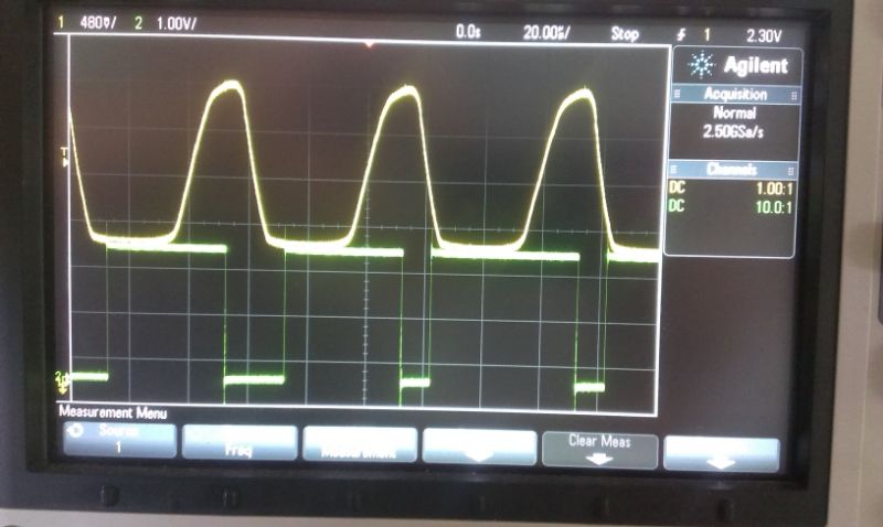
I noticed that my rising and falling edge values are not read from the middle of the signal but rather at the lowest and the highest values. So it means that the counting is made at the noisiest part of the signal. I don't know if it is the coding issue or it is the ADC sampling speed issue. I made a little photo of my signals>
citizen3942
Mon, 01 Sep 2014 08:22:19 +0000
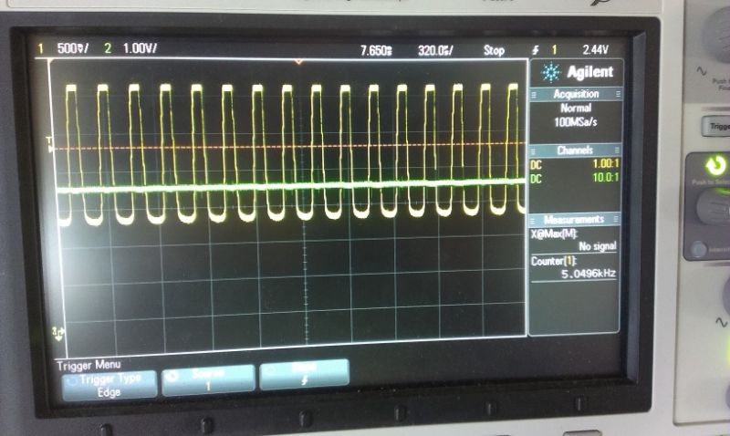
I tried to resynthesize the input signal to analog output but as a surprize i get static 3,8v signal with very tiny noise peaks and oscillation. This is why i dont get a correct reading.
Here is my test code:
void __attribute__((interrupt)) isr2() {
//digitalWrite(30, LOW);//set pin 28 low
  prevData = newData;//store previous value
  newData = analogRead(sensorPin);//get value from A0
   if (prevData < newData && newData >=THRESHOLD){//if positive slope
    digitalWrite(30, HIGH);//set pin 30 high
    totalTimer+=time;
    storIndex++; //increment storage index
    time=0; //reset time count
    if(storIndex==10){
    period=2*totalTimer/storIndex;//get average period
    //freq=SIGNALTICK/period;
    storIndex=0;//reset storage index
    totalTimer=0;//zero the total timer
  }
  }
  else{// if (prevData < THRESHOLD && newData >=THRESHOLD){//if negative slope
     digitalWrite(30, LOW);//set pin 30 low
  }
  analogWrite(A2,newData); //synthesize signal
  time++;
  // And tell the chip we have handled the interrupt by
  // clearing the flag.
  clearIntFlag(_TIMER_5_IRQ);
}
Here is my oscilloscope view:
majenko
Mon, 01 Sep 2014 08:36:09 +0000
analogWrite is PWM not true analog, and only works on pins marked with a ~