chipKIT® Development Platform
Inspired by Arduino™
- Get Started
- Learning
- Products
- Blog
- Beginner
For first time users of chipKIT modules. - Intermediate
For users who have a moderate exposure with chipKIT modules. - Advanced
For users who are experts with chipKIT modules. - Developers
- About Us
- Support
SoftSPI
| SoftSPI | |
|---|---|
| Quick Look | |
| Hardware | (External hardware) |
| Include | SoftSPI.h |
The SoftSPI library provides support for any number of bit-banged software SPI ports.
Detailed Introduction
The SPI protocol is a synchronous serial data protocol which contains one master (chipKIT) and one or more slave devices. It's designed for fast communication over short distances such as between two ICs on a PCB. The SoftSPI library only supports operation as an SPI master device.
Wiring
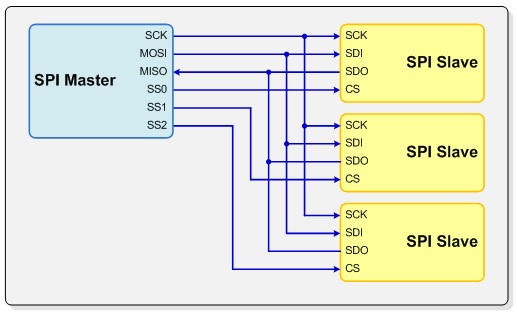
The SoftSPI library allows you to specify any pin for MOSI (SDO), MISO (SDI), SCK, and SS. As with the other SPI libraries the MOSI, MISO and SCK pins are common across all devices and the SS pin allows the master to select the slave devices to communicate with.
SPI Pin Definitions
| Label | Name | Definition |
|---|---|---|
| MOSI (SDO) | Master Out Slave In | Used for sending data from the master to the slave |
| MISO (SDI) | Master In Slave Out | Used for sending data from the slave to the master |
| SCK | Serial Clock | Syncronizes data transmission. |
| SS | Slave Select | A pin to signal to a chip that the master is trying to communcate with it. |
Introductory Programs
PmodJSTKSoftSpi
This demo blinks LED3 and LED4 on boards that have four LEDs, and at the same time, blinks the two LEDs on the PmodJSTK (2-axis joystick). It reads the state of the two buttons on the PmodJSTK, and turns LED1 and LED2 on and off based on the button state. The X and Y joystick position is read and placed into global variables, but not used by the demo itself.
/************************************************************************/
/*                                                                      */
/*  PmodJSTKSoftSpi -- Illustrate Use of SoftSPI Library with PmodJSTK  */
/*                                                                      */
/************************************************************************/
/*  Author: Gene Apperson                                               */
/*  Copyright 2011, Digilent Inc, All rights reserved.                  */
/************************************************************************/
/*
  This program is free software; you can redistribute it and/or
  modify it under the terms of the GNU Lesser General Public
  License as published by the Free Software Foundation; either
  version 2.1 of the License, or (at your option) any later version.

  This library is distributed in the hope that it will be useful,
  but WITHOUT ANY WARRANTY; without even the implied warranty of
  MERCHANTABILITY or FITNESS FOR A PARTICULAR PURPOSE.  See the GNU
  Lesser General Public License for more details.

  You should have received a copy of the GNU Lesser General Public
  License along with this library; if not, write to the Free Software
  Foundation, Inc., 51 Franklin St, Fifth Floor, Boston, MA  02110-1301  USA
*/
/************************************************************************/
/*  Module Description:                                                 */
/*                                                                      */
/* This example illustrates using the chipKIT SoftSPI library to        */
/* communicate with a Digilent PmodJSTK.                                */
/*                                                                      */
/* This demo blinks LED3 and LED4 on boards that have four LEDs, and at */
/* the same time, blinks the two LEDs on the PmodJSTK. It reads the     */
/* state of the two buttons on the PmodJSTK, and turns LED1 and LED2 on */
/* and off based on the button state. The X and Y joystick position is  */
/* read and placed into global variables, but not used by the demo      */
/* itself.                                                              */
/*                                                                      */
/************************************************************************/
/*  Revision History:                                                   */
/*                                                                      */
/*  11/21/2011(GeneApperson): Created                                   */
/*                                                                      */
/************************************************************************/


/* ------------------------------------------------------------ */
/*                Include File Definitions                      */
/* ------------------------------------------------------------ */

/* Pull in the SoftSPI library
*/
#include <SoftSPI.h>


/* ------------------------------------------------------------ */
/*                Local Type Definitions                        */
/* ------------------------------------------------------------ */

#define	cntBlinkInit	50000

#define  SPI_PORT  1

#if (SPI_PORT == 1)

#define  pinSS    24
#define  pinMOSI  25
#define  pinMISO  26
#define  pinSCK   27

#elif (SPI_PORT == 2)

#define  pinSS    32
#define  pinMOSI  33
#define  pinMISO  34
#define  pinSCK   35

#elif (SPI_PORT == 3)

#define  pinSS    40
#define  pinMOSI  41
#define  pinMISO  42
#define  pinSCK   43

#endif

/* ------------------------------------------------------------ */
/*                Global Variables                              */
/* ------------------------------------------------------------ */

int      cntBtnBlink;
uint8_t  fbLedPmod;
uint8_t  fbBtnPmod;
int      xcoPmod;
int      ycoPmod;
int      fLed3;
int      fLed4;

/* Unlike many chipKIT/Arduino libraries, the SoftSPI library doesn't
** automatically instantiate any interface objects. It is necessary
** to declare an instance of one of the interface objects in the
** sketch.
*/
SoftSPI    spi;

/* ------------------------------------------------------------ */
/*                Local Variables                               */
/* ------------------------------------------------------------ */


/* ------------------------------------------------------------ */
/*                Forward Declarations                          */
/* ------------------------------------------------------------ */


/* ------------------------------------------------------------ */
/*                Procedure Definitions                         */
/* ------------------------------------------------------------ */
/***  setup
**
**  Parameters:
**    none
**
**  Return Value:
**    none
**
**  Errors:
**    none
**
**  Description:
**    Initialize the system.
*/

void setup() {
    DeviceInit();
    AppInit();
}

/* ------------------------------------------------------------ */
/***  loop
**
**  Parameters:
**    none
**
**  Return Value:
**    none
**
**  Errors:
**    none
**
**  Description:
**    Main application loop.
*/

void loop() {
    AppTask();
}

/* ------------------------------------------------------------ */
/***  DeviceInit
**
**  Parameters:
**    none
**
**  Return Value:
**  none
**
**  Errors:
**  none
**
**  Description:
**    Perform basic board/device level initialization.
*/

void DeviceInit() {
    /* Set the LED pins to be outputs. Some boards support more
    ** than two LEDs. On those boards, also blink the additional
    ** LEDs.
    */
    pinMode(PIN_LED1, OUTPUT);
    pinMode(PIN_LED2, OUTPUT);
#if defined(PIN_LED3)
    pinMode(PIN_LED3, OUTPUT);
#endif
#if defined(PIN_LED4)
    pinMode(PIN_LED4, OUTPUT);
#endif
    /* Initialize the SPI port.
    ** Note: The pmodJSTK requires a delay of at least 6uS between
    ** bytes, so the delay is set to 6uS below.
    */
    spi.begin(pinSS, pinMOSI, pinMISO, pinSCK);
    spi.setSpeed(250000);
    spi.setMode(SSPI_MODE0);
    spi.setDirection(SSPI_SHIFT_LEFT);
    spi.setDelay(6);
}

/* ------------------------------------------------------------ */
/***	AppInit
**
**  Parameters:
**    none
**
**  Return Value:
**    none
**
**  Errors:
**    none
**
**  Description:
**    Perform application level initialization. Call the various
**    init functions to initalize the application subsystems.
*/

void AppInit() {
    /* Init program state variables.
    */
    cntBtnBlink = cntBlinkInit;
    fbLedPmod = 0x01;
    fbBtnPmod = 0;
    xcoPmod = 0;
    ycoPmod = 0;
    /* Start with LED3 on and LED4 off
    */
    fLed3 = HIGH;
    fLed4 = LOW;
}

/* ------------------------------------------------------------ */
/***	AppTask
**
**  Parameters:
**    none
**
**  Return Value:
**    none
**
**  Errors:
**    none
**
**  Description:
**    Perform main application functions. This is called once
**    each time through the main program loop.
*/

void AppTask() {
    unsigned int	dwBtn;
    /* Check the state of button 1 on the PmodJSTK and set LED 1
    ** accordingly
    */
    dwBtn = fbBtnPmod & 0x01;

    if (dwBtn == 0) {
        digitalWrite(PIN_LED1, LOW);
    } else {
        digitalWrite(PIN_LED1, HIGH);
    }

    /* Check the state of button 2 and set LED 2 accordingly
    */
    dwBtn = fbBtnPmod & 0x02;

    if (dwBtn == 0) {
        digitalWrite(PIN_LED2, LOW);
    } else {
        digitalWrite(PIN_LED2, HIGH);
    }

    /* Check if it is time to blink LED3 & LED4 and update
    ** the joystick.
    */
    cntBtnBlink -= 1;

    if (cntBtnBlink == 0) {
#if defined(PIN_LED3)
        digitalWrite(PIN_LED3, fLed3);
        fLed3 = (fLed3 == HIGH) ? LOW : HIGH;
#endif
#if defined(PIN_LED4)
        digitalWrite(PIN_LED4, fLed4);
        fLed4 = (fLed4 == HIGH) ? LOW : HIGH;
#endif
        /* Toggle the setting for the LEDs on the joystick.
        */
        fbLedPmod ^= 0x03;
        /* Update the joystick.
        */
        ReadJoystick(fbLedPmod, &fbBtnPmod, &xcoPmod, &ycoPmod);
        cntBtnBlink = cntBlinkInit;
    }
}

/* ------------------------------------------------------------ */
/***  ReadJoystick
**
**  Parameters:
**    fbLed	- LED state to set
**    pfbBtn	- variable to receive button state
**    pxco	- pointer to var to receive x coordinate
**    pyco	- pointer to var to receive y coordinate
**
**  Return Value:
**    none
**
**  Errors:
**    none
**
**  Description:
**    Read the current position of the joystick and buttons.
*/
void ReadJoystick(uint8_t fbLed, uint8_t * pfbBtn, int * pxco, int * pyco) {
    uint8_t    rgbSnd[5];
    uint8_t    rgbRcv[5];
    int	     ib;

    /* Initialize the transmit buffer.
    */
    for (ib = 0; ib < 5; ib++) {
        rgbSnd[ib] = 0x50 + ib;
    }

    rgbSnd[0] = fbLedPmod + 0x80;  //first byte sent sets the LEDs
    /* Bring SS low to begin the transaction.
    */
    spi.setSelect(LOW);
    /* Wait 10us for Pmod to become ready
    */
    Delay10us();
    /* Send the data to the Pmod and get the response.
    */
    spi.transfer(5, rgbSnd, rgbRcv);
    /* Bring SS high to end the transaction.
    */
    spi.setSelect(HIGH);
    /* Set up the return values.
    */
    *pfbBtn = rgbRcv[4] >> 1;
    *pxco = (uint16_t)((rgbRcv[1] << 8) + rgbRcv[0]);
    *pyco = (uint16_t)((rgbRcv[3] << 8) + rgbRcv[2]);
}

/* ------------------------------------------------------------ */
/***  Delay10us
**
**  Parameters:
**    none
**
**  Return Value:
**    none
**
**  Errors:
**    none
**
**  Description:
**    Delay loop for ~10uS
*/

void Delay10us() {
    volatile int		cnt;

    for (cnt = 0; cnt < 100; cnt++) {
    }
}

/* ------------------------------------------------------------ */

/************************************************************************/
Full library usage
SoftSPI
Constants
Flags for SPI Modes
| Name | Value | Clock Polarity (CPOL/CKP) |
Clock Phase (CPHA) |
Clock Edge (CKE/NCPHA) |
|---|---|---|---|---|
| SSPI_MODE0 | 0x00 | 0 | 0 | 1 |
| SSPI_MODE1 | 0x04 | 0 | 1 | 0 |
| SSPI_MODE2 | 0x08 | 1 | 0 | 1 |
| SSPI_MODE3 | 0x0C | 1 | 1 | 0 |
Flags for Shift Direction
| Name | Value |
|---|---|
| SSPI_SHIFT_LEFT | 0 |
| SSPI_SHIFT_RIGHT | 1 |
Default SPI Clock Speed
| Name | Value |
|---|---|
| SSPI_SPEED_DEFAULT | 500000 |
Constructors
SoftSPI()
SoftSPI();
Initialize the object before use.
SoftSPI(uint8_t pinSSt, uint8_t pinMOSIt, uint8_t pinMISOt, uint8_t pinSCKt)
SoftSPI(uint8_t pinSSt, uint8_t pinMOSIt, uint8_t pinMISOt, uint8_t pinSCKt);
- pinSS digital pin to use for SS
- pinMOSI digital pin to use for MOSI
- pinMISO digital pin to use for MISO
- pinSCK digital pin to use for SCK
Public Functions
begin(void)
bool begin(void);
Pepare the object for use. Set the pin directions, and set SS HIGH and the clock to the idle state
begin(uint8_t pinSSt, uint8_t pinMOSIt, uint8_t pinMISOt, uint8_t pinSCKt))
bool begin(uint8_t pinSSt, uint8_t pinMOSIt, uint8_t pinMISOt, uint8_t pinSCKt);
Pepare the object for use. Set the pin directions, and set SS HIGH and the clock to the idle state
- pinSS digital pin to use for SS
- pinMOSI digital pin to use for MOSI
- pinMISO digital pin to use for MISO
- pinSCK digital pin to use for SCK
end()
void end();
Deinitialize the object. Release all of the pins, by making them all inputs.
setSpeed(uint32_t spd)
void setSpeed(uint32_t spd);
Set the SPI clock speed to the closest supported value to the requested clock speed.
setMode(uint16_t mod)
void setMode(uint16_t mod);
Set the SPI mode to the requested value. Default to mode 0 if an unsupported value is specified.
setDirection(int dir)
void setDirection(int dir);
Set the shift direction to the requested value. Default to shift left if an unsupported value is specified.
setDelay(int dly)
void setDelay(int dly);
dly max 4294
Set the interbyte delay to the specified value.
The relationship between the delay count value and the delay in microseconds has been determined experimentally to be approximately: d ~ P * (47 + 880/100 * n) where P is period of processor clock. This yields the delay count to be: n = ((80*d - 47) * 100) / 880 Note: this calculations assumes that the processor clock is 80Mhz.
setSelect(uint8_t sel)
void setSelect(uint8_t sel);
Set's the SS pin High / Low specified by the sel parameter.
transfer(uint8_t bVal)
uint8_t transfer(uint8_t bVal);
Send the specified byte to the slave and return the byte received from the slave.
transfer(uint16_t cbReq, uint8_t * pbSnd, uint8_t * pbRcv)
void transfer(uint16_t cbReq, uint8_t * pbSnd, uint8_t * pbRcv);
transfer(uint16_t cbReq, uint8_t * pbSnd)
void transfer(uint16_t cbReq, uint8_t * pbSnd);
Send the requested number of bytes, storing the bytes received in the specified buffer.
- cbReq - number of bytes to transfer
- pbSnd - buffer containing bytes to send
- pbRcv - buffer to hold bytes received
transfer(uint16_t cbReq, uint8_t bPad, uint8_t * pbRcv)
void transfer(uint16_t cbReq, uint8_t bPad, uint8_t * pbRcv);
This function will send the requested bytes to the SPI slave device, discarding the bytes received from the slave.
- cbReq - number of bytes to transfer
- pbSnd - buffer containing bytes to send
External Links
- [https://github.com/chipKIT32/chipKIT-core/tree/master/pic32/libraries/SoftSPI https://github.com/chipKIT32/chipKIT-core/tree/master/pic32/libraries/SoftSPI] - The github repository for the chipKIT SoftSPI Library.
- en.wikipedia.org/wiki/Serial_Peripheral_Interface_Bus - Serial Peripheral Interface Bus