chipKIT® Development Platform
Inspired by Arduino™
- Get Started
- Learning
- Products
- Blog
- Beginner
For first time users of chipKIT modules. - Intermediate
For users who have a moderate exposure with chipKIT modules. - Advanced
For users who are experts with chipKIT modules. - Developers
- About Us
- Support
Last edit: 2021-03-21 22:34 by Majenko
ChipKIT Cmod
| chipKIT Cmod | |
|---|---|
 | |
| Specifications | |
| Controller | PIC32MX150F128D |
| Flash | 128kB |
| RAM | 32kB |
| Speed | 40/50 MHz |
| Information | |
| Board Define | _BOARD_CMOD_ |
| Links | |
| Designer | Digilent Inc. |
| Product Page | digilentinc.com |
| User Guide | chipkit_cmod_rm.pdf |
| Schematic | chipkit_cmod_sch.pdf |
| Tech Support | chipkit.net/forum |
| Board Files | Eagle (ZIP) |
| Bootloader HEX | Bootloader Image (ZIP) |
| Purchase From | Microchip |
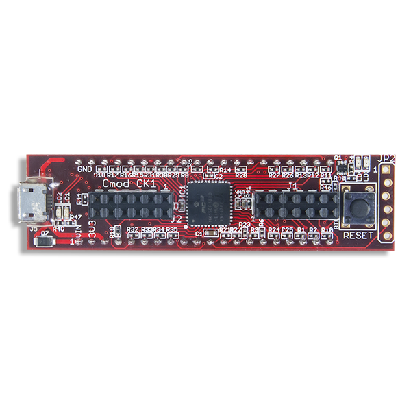
The chipKIT Cmod is a chipKIT compatible board from Digilent. It combines a Microchip® PIC32MX150F128D microcontroller with a convenient 600-mil, 40-pin DIP package and two Digilent Pmod connectors. Digilent’s Cmod boards are ideally suited for breadboards or other prototype circuit designs where the use of small surface mount packages is impractical.
The Board Design
- PIC32MX150F128D MCU
- 128K Flash, 32K RAM
- PPS, two SPI, two I2C, and two UART connectors
- 13 Analong Inputs with 10-bit ADC
- 33 GPIO pins
- Two 12-pin Pmod ports
- Convenient 600-mil 2x20-pin DIP package
- Two user LEDs
Useful Board Pins
LEDs
| LED Name | Description |
|---|---|
| LD1 | USB TX Activity LED |
| LD2 | USB RX Activity LED |
| LD3 | Digital pin 14 |
| LD4 | Digital pin 12 |
Analog Inputs
| Analog Input | Digital Pin |
|---|---|
| A0 | 18 |
| A1 | 19 |
| A2 | 20 |
| A3 | 21 |
| A4 | 22 |
| A5 | 23 |
| A6 | 24 |
| A7 | 25 |
| A8 | 26 |
| A9 | 17 |
| A10 | 16 |
| A11 | 13 |
| A12 | 12 |
Serial Objects
| Serial Object | UART | TX Pin | RX Pin |
|---|---|---|---|
| Serial | USB/UART1 | 23 | 5 |
| Serial1 | UART2 | 20 | 21 |
I2C
| I2C Object | Channel | SDA Pin | SCL Pin |
|---|---|---|---|
| DTWI0 / Wire | 1 | SDA1 (4) | SCL1 (38) |
| DTWI1 | 2 | SDA2 (22) | SCL2 (23) |
SPI
| SPI Object | Channel | SS | MOSI Pin | MISO Pin | SCK Pin |
|---|---|---|---|---|---|
| DSPI0 / SPI | 1 | 24 | 25 | 35 | 16 |
| DSPI1 / SPI | 2 | 33 | 36 | 32 | 17 |
Pinout Table
| DIP Pin # | chipKIT Pin # | Connector Pin # | PIC32 Pin # | PIC32 Signal | Notes |
|---|---|---|---|---|---|
| 1 | - | - | N/A | VIN/External Power | |
| 2 | - | - | 28/40 | VDD | VCC3V3 |
| 3 | - | - | - | N/A | USB5V0/External 5V Power for USB |
| 4 | 4 | - | 1 | RPB9/SDA1/CTED4/PMD3/RB9 | OC3 |
| 5 | 5 | - | 2 | RPC7/PMA0/RC7 | |
| 6 | 6 | J1-08 | 3 | RPC7/PMA0/RC7 | |
| 7 | 7 | J1-07 | 4 | RPC8/PMA5/RC8 | INT3 |
| 8 | 8 | J1-10 | 5 | RPC9/CTED7/PMA6/RC9 | |
| 9 | - | - | 18 | MCLR | RESET |
| 10 | 10 | - | 8 | PGED2/RPB10/CTED11/PMD2/RB10 | IC2 |
| 11 | 11 | - | 9 | PGEC2/RPB11/PMD1/RB11 | |
| 12 | 12/A12 | - | 10 | AN12/PMD0/RB12 | LD4 |
| 13 | 13/A11 | - | 10 | AN11/RPB13/CTPLS/PMRD/RB13 | OC5/INT2 |
| 14 | 14 | - | 12 | PGED(4)/TMS/PMA10/RA10 | LD3 |
| 15 | 15 | - | 13 | PGEC(4)/TCK/CTED8/PMA7/RA7 | |
| 16 | 16/10 | J1-04 | 14 | CVREF/AN10/C3INB/RPB14/SCK1/CTED5/PMWR/RB14 | |
| 17 | 17/A9 | J2-10 | 15 | AN9/C3INA/RPB15/SCK2/CTED6/PMCS1/RB15 | |
| 18 | 18/A0 | - | 19 | VREF+/CVREF+/AN0/C3INC/RPA0/CTED1/RA0 | TCK2 |
| 19 | 19/A1 | - | 20 | VREF-/CVREF-/AN1/RPA1/CTED2/RA1 | |
| 20 | 20/A2 | J2-02 | 21 | PGED1/AN2/C1IND/C2INB/C3IND/RPB0/RB0 | U2TX |
| 21 | 21/A3 | J2-03 | 22 | PGEC1/AN3/C1INC/C2INA/RPB1/CTED12/RB1 | U2RX |
| 22 | 22/A4 | J2-01 | 23 | AN4/C1INB/C2IND/RPB2/SDA2/CTED13/RB2 | OC4 |
| 23 | 23/A5 | - | 24 | AN5/C1INA/C2INC/RTCC/RPB3/SCL2/RB3 | U1TX |
| 24 | 24/A6 | J1-01 | 25 | AN6/RPC0/RC0 | SS1 |
| 25 | 25/A7 | J1-02 | 26 | AN7/RPC1/RC1 | IC5/SDO1 |
| 26 | 26/A8 | - | 27 | AN8/RPC2/PMA2/RC2 | TCK5 |
| 27 | 27 | - | 32 | TDO/RPA8/PMA8/RA8 | TCK3 |
| 28 | - | - | - | - | Not Connected |
| 29 | 29 | - | 33 | SOSCI/RPB4/RB4 | OC1 |
| 30 | 30 | J1-09 | 34 | SOSCO/RPA4/T1CK/CTED9/RA4 | TCK1 |
| 31 | 31 | - | 35 | TDI/RPA9/PMA9/RA9 | IC3 |
| 32 | 32 | J2-09 | 36 | RPC3/RC3 | TCK4/SDI2 |
| 33 | 33 | J2-07 | 37 | RPC4/PMA4/RC4 | INT1/SS2 |
| 34 | 34 | J2-04 | 38 | RPC5/PMA3/RC5 | |
| 35 | 35 | J1-03 | 41 | PGED3/RPB5/PMD7/RB5 | SDI1 |
| 36 | 36 | J2-08 | 42 | PGEC3/RPB6/PMD6/RB6 | IC1/SDO2 |
| 37 | 37 | - | 43 | RPB7/CTED3/PMD5/INT0/RB7 | IC4/INT4 |
| 38 | 38 | - | 44 | RPB8/SCL1/CTED10/PMD4/RB8 | OC2 |
| 39/40 | - | - | 6/16/29/39 | VSS/AVSS | GND |